
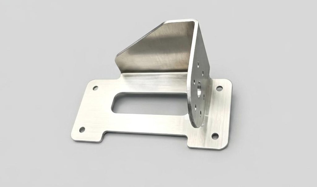
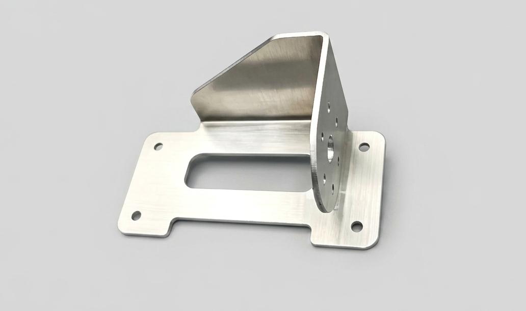
Aluminum Box-Type Bracket with Laser Cutting
- Material: AL 6061-T6
- Size: 30*120*60
- Process: Laser Cutting + Bending + Welding
- Surface treatment: None
This is a compact aluminium box-type bracket produced by the laser cutting and press brake bending process as its larger counterpart. All profiles, holes, and cutouts are laser cut from flat sheet first, followed by multiple sequential bends to form the three-dimensional box, and a final deburring pass. At 30X120X60 mm, the structure is noticeably more compact, with all bent features sitting much closer together.
Machining Challenges
This small bracket faces the same category of challenges as the larger box, but the way those challenges present themselves is shaped by the tighter dimensions.
Minimal clearance between bent faces restricts tooling access. A 30X60 mm cross-section means the distances between adjacent bend lines are very short. Standard press brake upper and lower dies frequently can’t complete later bends without colliding with already-formed side walls. Narrow or purpose-specific tooling is typically required, and the bend sequence has to be planned around what the tooling can physically reach — not just what order makes dimensional sense.
Cumulative angular error has more immediate dimensional impact at small scale. Within a 60 mm height, the positional effect of accumulated bend angle deviation is proportionally larger than on a big part. The same half-degree of angular error that might be harmless across 150 mm of height produces an offset approaching the ±0.1 mm tolerance boundary across only 60 mm. There’s simply less geometric margin to absorb errors.
Corner tearing risk remains. The ratio of wall thickness to bend radius at tight corners can be less favourable on small parts, and tensile stress concentration at inside corners is just as capable of initiating tearing in thin aluminium sheet. Relief notches are still needed.
How It’s Managed
| Stage | Approach |
| Bend sequence planning | Bend order planned around the physical access constraints of the compact cross-section — the most space-restricted bends go first, before side walls are in place to block tooling |
| Narrow tooling | Purpose-specific narrow dies selected for this box geometry, ensuring adequate clearance at every bend step |
| Precise springback compensation | At this scale, each bend’s compensation value needs to be verified by trial bending before committing to production — standard lookup values are not reliable enough |
| Corner relief notches | Process relief cuts at all inside corners to distribute stress and prevent tearing |
| Post-bend correction | Full dimensional check and correction pass after all bending is complete, bringing critical faces and hole positions within final tolerance |