Laser Cutting
Complex Profiles, Formed in a Single Cut
Fiber Laser Cutting · Tube Laser Cutting · Precision Laser Cutting
Carbon steel, stainless steel, aluminum alloy, copper, titanium alloy—if it is metal, we can cut it.
IATF 16949 · ISO 9001 · Wide Thickness Range: 0.1 mm to 30 mm
What Problems Can Laser Cutting Solve for You?
Reduce Secondary Operations with Direct Forming
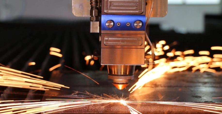
Laser cutting is a precision manufacturing process used to produce custom laser cut metal parts. With CNC-controlled beam guidance, the final contour is obtained directly, eliminating the need for tooling or subsequent blanking operations.
Complex Profiles Completed in One Pass
Irregular cut-outs, grids, curves, and More. Reduce punching, wire cutting, plasma cutting, and other secondary processes to shorten lead times.
No More Distortion Concerns for Thin Sheets
For thin stainless steel, aluminum alloy, and copper sheets—materials prone to heat-induced distortion—laser cutting provides a more stable and controlled solution.
Wide Material Compatibility
Carbon steel, cold-rolled sheet, hot-rolled sheet, Q235, Q355
Stainless steel grades 201 / 304 / 316
Aluminum sheet, aluminum alloy
Copper sheet, brass, pure copper
Galvanized sheet, galvalume sheet, electrolytic sheet
Alloy steel, spring steel, tool steel thin sheet
Multiple Cutting Methods—Always the Right One for Your Part
Different laser cutting methods are suited to different materials, thicknesses, tolerance requirements, and cut-face quality.
Fiber Laser Cutting
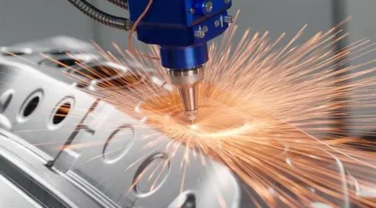
Ideal for sheet metal parts and custom fabrication projects, offering high cutting speed and low operating cost.
Typical Parts: Enclosure panels, sheet metal housings, structural brackets.
Tube Laser Cutting
Suitable for round tubes, square tubes, and special-shaped tubes, with the capability for intersecting line cutting.
Typical Parts: Vehicle frame tubes, guardrails, structural members.
Precision Laser Cutting
Suitable for thin-gauge materials, intricate geometries, and high-density part layouts.
Typical Parts: Electronic components, medical devices, precision shims.
Key Process Flow Differences:
| Process | Core Process Flow (Key Steps Distinguishing Each Method) |
| Fiber Laser Cutting | Laser source → Fiber transmission → Focusing head → Assist gas slag removal → CNC motion cutting |
| Tube Laser Cutting | Tube loading → Rotary chuck clamping → Laser head & rotary axis coordination → Cope cutting / hole cutting / parting |
| Precision Laser Cutting | High power density → Narrow pulse control → Minimal heat-affected zone → Micron-level positioning → High-precision motion platform |
One Table—Full Clarity on Our Cutting Capabilities
The following data represents general reference ranges. Actual capability is subject to real-world testing with your specific drawings.
| Process | Accuracy Grade | Cut-Face Roughness | Min. Kerf Width | Standard Thickness Range | Common Materials |
| Fiber Laser Cutting | ±0.05-0.1mm | Ra 6.3-12.5µm | 0.1-0.3mm | 0.5-20mm(carbon steel) | Carbon steel, stainless steel, aluminum alloy, galvanized sheet |
| Tube Laser Cutting | ±0.1-0.3mm | Ra 12.5-25µm | 0.2-0.5mm | Tube Diameter 10-200mm | Carbon steel tube, stainless steel tube, aluminum tube, special-shaped tube |
| Precision Laser Cutting | ±0.01-0.03mm | Ra 1.6-3.2µm | 0.02-0.1mm | 0.05-2mm | Stainless steel foil, copper foil, nickel alloy, polymer |
How Is Quality Assured? Five Stages, Every Stage Documented
- Drawing & Path Optimization → Pre-cut path simulation to prevent thermal concentration and sharp-corner burn-through.
- Material Inspection → Verification of material grade, thickness, and surface condition against process parameters.
- Process Monitoring → Real-time recording of focal position, assist gas pressure, and cutting speed.
- First Article Inspection → Full inspection of contour accuracy, cut-face quality, and dimensions before batch production.
- Pre-Shipment Inspection → Accompanied by dimensional reports and cut-face photographs. Surface roughness measurement available on request.
Available Inspection Capabilities:
Cutting Is Just the Beginning—We Also Provide Precision Secondary Machining
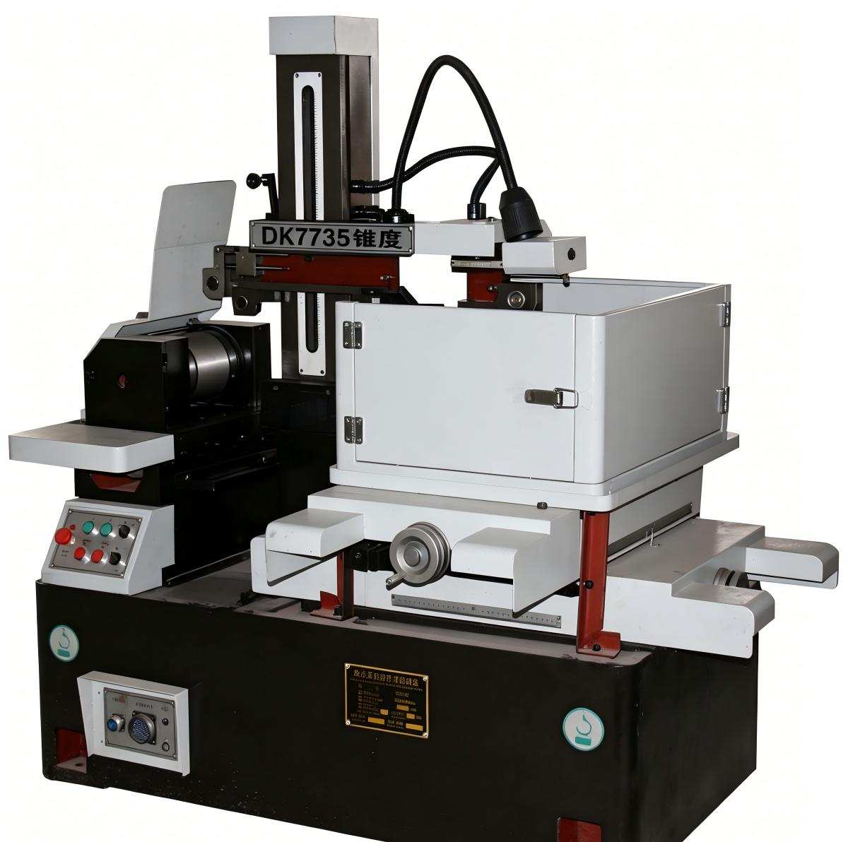
Laser cutting takes care of the contour forming. For critical dimensions such as mating surfaces, tapped holes, and datum faces, we offer subsequent precision machining services.
What We Can Do:
- Drilling, milling, tapping, counterboring, and chamfering on cut parts
- Post-machining dimensional accuracy achievable to IT7-IT8 grade
- Surface roughness achievable to Ra 1.6-3.2 µm
What Does This Mean For You?
- No need to source a separate machining supplier—we handle everything in one stop
- Reduced handling and positioning errors
- Laser cutting + localized precision machining = the ideal balance of efficiency and accuracy
Other Surface Finishing Options:
Sandblasting · Brushing · Grinding · Deburring · Passivation · Coating
| Treatment Options | Application | Description |
| Sandblasting | Scale removal, improved surface uniformity | Uniform matte finish, reduced roughness |
| Brushing | Decorative surfaces, housings | Uniform grain direction, aesthetically pleasing and durable |
| Deburring | Thin-sheet and precision parts | Removes heat-affected dross and sharp edges |
| Passivation | Stainless steel parts | Enhances corrosion resistance |
Design Guidelines for Laser-Cut Parts
Not every geometry is optimal for laser cutting. Good design practice improves cut quality and efficiency. The following are fundamental guidelines:
Minimum Feature Sizes and Detail
• Minimum hole diameter ≥ material thickness
• Minimum slot width ≥ material thickness
• Sharp corners should be replaced with radii of R ≥ 0.5 mm
Heat Input Management
• Avoid dense arrays of microholes
• Slender cantilevered features are prone to distortion; segmented cutting or tab-and-slot design is recommended
Recommended Material Thickness
• Standard sheet: 0.5-20 mm
• Precision cutting: 0.05-2 mm
• High-reflectivity materials (copper, aluminum) require specialized process parameters
Does Your Part Structure Need Optimization?
Upload Your Drawings for a Free Analysis.
Is Laser Cutting the Right Process for Your Parts?
Not every part is suitable for laser cutting. We’ll help you make a quick judgment.
| Better Suited for Laser Cutting | May Not Be Suitable |
| Thin to medium-gauge sheet (0.5-20 mm) | Thickness exceeding 30 mm (waterjet or plasma is more cost-effective) |
| Complex profiles or frequent design changes | High-volume, simple identical parts (stamping is more economical) |
| Stainless steel, aluminum alloy, carbon steel, galvanized sheet | Zero tolerance for heat-affected zones |
| Low volume, high-mix, short lead time | Mirror-finish cut face with zero oxide layer required |
| No tooling required, rapid forming | High-reflectivity materials such as copper and aluminum (require specialist processes) |
Not sure? Send us your drawings for a free evaluation.
If laser cutting isn’t the right fit, We’ll tell you honestly—and recommend a more suitable process.
Questions You May Have—Answered Directly
Upload Your Drawings – Get Answers in Three Steps
✅Free Assessment | ✅Fast Response | ✅Honest Feedback
Supported formats: STEP, IGES, DXF, DWG, PDF. All drawings are kept strictly confidential.
We analyze whether your part is suitable for laser cutting, which method is optimal, and where potential risks may exist.
We provide a quotation, lead time, and a description of achievable accuracy and cut-face quality.
Upload Your Drawings to Start the Evaluation
We process a large number of drawing evaluations every working day. Submit as early as possible to receive the solution sooner.