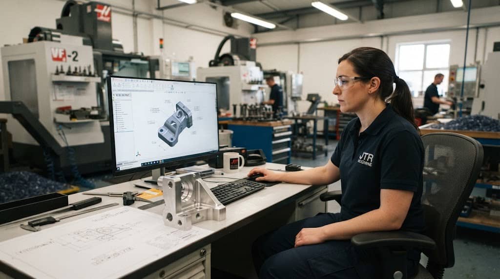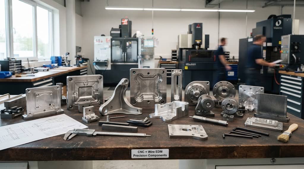


Geometric Dimensioning and Tolerancing (GD&T) helps engineers define how CNC machined parts must fit, align, and function. Flatness, position, and perpendicularity are three important controls. Each addresses a different geometrical need.
Incorrect GD&T callouts can lead to assembly problems, higher inspection costs, and delays in production. The answer is not to tighten up all of the tolerances. The goal is to define the geometry pertinent to the part’s function that can be manufactured and inspected with confidence.
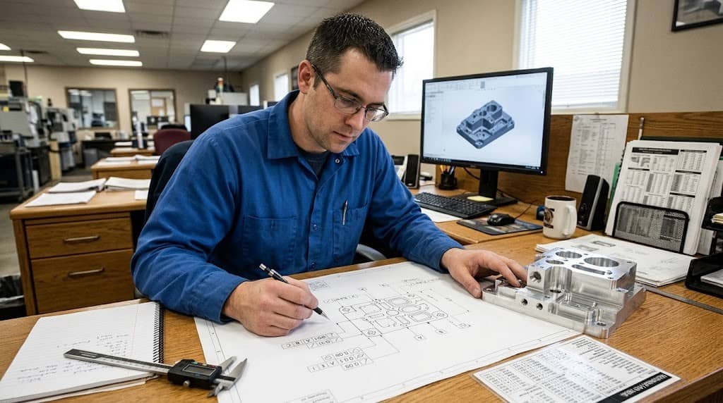
What Is GDT In CNC?
GD&T is a standardized method for specifying allowable geometric variation on engineering drawings and digital product definitions. It allows designers, machinists, and quality engineers to understand the same requirements.
Dimensional tolerances control size and spacing. GD&T controls such geometric characteristics as form, orientation, and feature location.
A mounting hole can be the right diameter, but be in the wrong place. Similarly, a plate can meet length and width requirements, but have a warped mounting surface.
GD&T “Good” links the drawing requirements to the assembly needs and inspection methods. The ASME Y14.5 Dimensioning and Tolerancing standard is the governing document for the use and interpretation of GD&T under the referenced standard version.
Position Tolerance Controlling the Location of Holes
Position tolerance controls the position of a feature relative to its theoretical perfect position. This is often used for mounting holes, dowel holes, and hole patterns that need to line up with mating components.
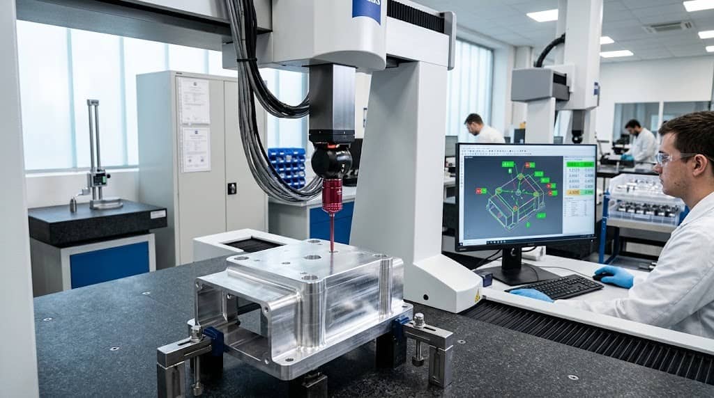
When do you specify position tolerance?
Say we have an aluminum housing with four mounting holes. Each hole satisfies its diameter constraint, but one hole is displaced from its desired location. The housing might not mate properly with its mating component.
A position tolerance defines a geometric tolerance zone in which the controlled feature has to lie.
To put it correctly:
- Choose functional datums. For example, datum A may establish the mounting surface, and datums B and C may establish lateral location.
- Where the applicable GD&T standard requires exact feature locations, theoretically define them using basic dimensions.
- Tolerance should be set according to assembly needs, clearance and manufacturing capability
- When the feature departs from maximum material condition, consider material condition modifiers when the design benefits from additional positional tolerance.
There are certain functional applications where MMC is useful, but it should not be applied to every hole automatically.
How do you check position tolerance?
A Coordinate Measuring Machine ( CMM ) can measure the hole locations relative to the specified datum reference frame. Appropriate functional gauges can also verify assembly-related requirements.
The inspection setup shall adhere to the datum scheme of the drawing. The measurement of hole coordinates from an unrelated edge does not, by itself, show compliance with the specified position tolerance.
Flatness Tolerance: Controlling Surface Deviation
Flatness is how far a surface deviates from a theoretically perfect plane. This is especially important for mounting plates, sealing faces, fixture surfaces, and components, which require stable contact.
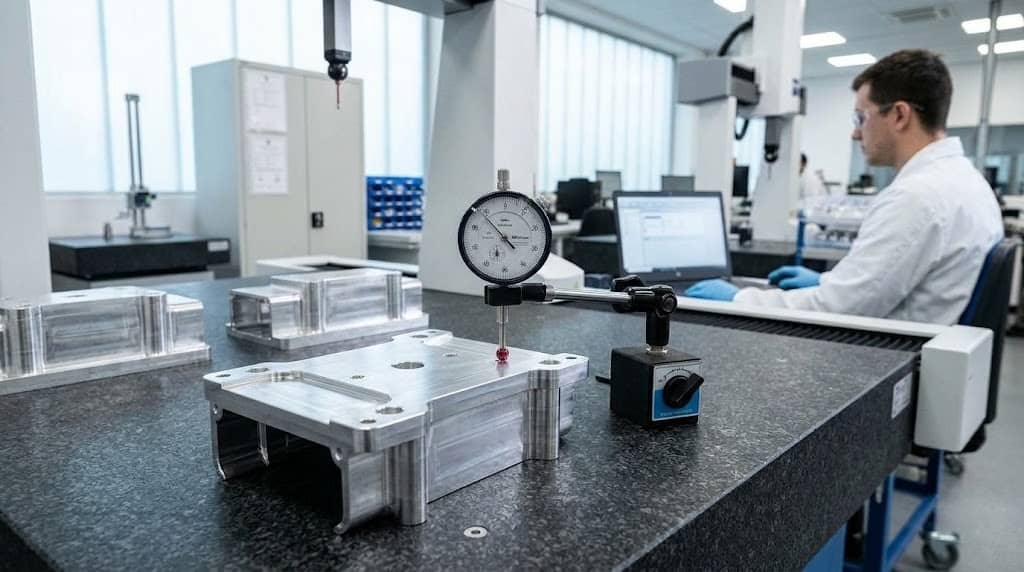
How do you specify flatness?
A tolerance of flatness is a zone between two parallel planes. The entire controlled surface must be within that zone.
Flatness is a geometric tolerance and does not require a datum reference. This is unlike parallelism that controls the orientation of a surface relative to a specified datum.
For example, an aluminum mounting plate may meet the thickness requirement, but it may rock on a fixture due to the surface being warped.
Common causes:
- Residual stress released during material removal.
- Uneven or excessive clamping force.
- Heat generated in machining.
- Non-uniform removal of stock and thin-wall geometry.
- Distortion after unclamping or finishing.
The risks can be reduced by manufacturers by reviewing the machining sequence, fixture design, cutting strategy, and material condition. Some parts are especially sensitive to distortion and can benefit from intermediate machining and inspection.
How to check flatness?
Depending on the part geometry and tolerance, appropriate methods are a surface plate with an indicator, a CMM, or another appropriate measurement system.
The inspection method and measurement points shall be suitable for the specified surface. A few isolated readings may not reveal all relevant surface deviations.
Perpendicularity Tolerance: Keeping 90-Degree Relationships Under Control
Perpendicularity is a control to ensure that a surface or feature is maintained at the required 90 degrees to a datum.
Typical uses are machined brackets, housings, mounting faces, and holes whose axes must be properly aligned with another surface.
How shall perpendicularity be specified?
First determine the feature that is important to assembly. Does a side wall have to be square to a base, or a hole axis have to be perpendicular to a mounting face?
Then pick the datum that is the functional reference. The mounting surface can be datum A when other features must be perpendicular to it.
The tolerance zone depends on the feature being controlled. The zone for a surface consists of two parallel planes with an orientation of 90° to the datum plane. The specified tolerance zone for an axis may be cylindrical, depending on the applicable callout.
For example, a mounting hole drilled at an angle to the base can cause the fastener to enter unevenly or the assembled component to sit incorrectly.
A CMM can evaluate the controlled surface or axis in relation to the datum reference frame. A precision square and indicator may be applicable for surface checks as well.
The inspection method must evaluate the specified geometric relationship, not just whether two visible edges appear square.
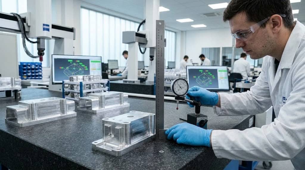
Position vs. Flatness vs. Perpendicularity
| GD&T control | What it controls | Typical application | Datum required? |
| Position | Feature location | Mounting holes and hole patterns | Usually, depending on the callout |
| Flatness | Surface form | Sealing and mounting surfaces | No |
| Perpendicularity | Orientation relative to a datum | Side walls and hole axes | Yes |
These controls cannot be interchanged. Hole position may be acceptable, but the axis orientation may not be acceptable. A surface can be flat but not normal to its mounting datum.
Select the control that represents the real functional need. More geometric tolerances than actually needed for the design may serve only to increase the cost of manufacture and inspection.
Typical GD&T Mistakes That Drive Up CNC Machining Costs
Precision parts can be harder to manufacture and verify if they have several drawing errors.
- Overly tight tolerances: Tight tolerances on every feature can contribute to machining and inspection costs, without improving functionality.
- Wrong datum selection: If a datum scheme does not represent the actual assembly conditions, it can cause confusion in manufacturing and inspection.
- Geometric controls are confusing: flatness, parallelism, position, and perpendicularity are all used to satisfy different requirements. Replacing one with another may leave a crucial design condition uncontrolled.
- Unclear inspection requirements: A drawing may call for a tight tolerance without regard to how the feature will be measured or how the part will be positioned during inspection.
- Not considering the post-processing: The anodizing and other finishing operations can influence the final dimensions and the fits. Check critical features against the required finished condition.
For further manufacturing considerations, please see JTR’s CNC machining service. Engineers looking at manufacturing partners can also see what to look for when picking CNC machining services.
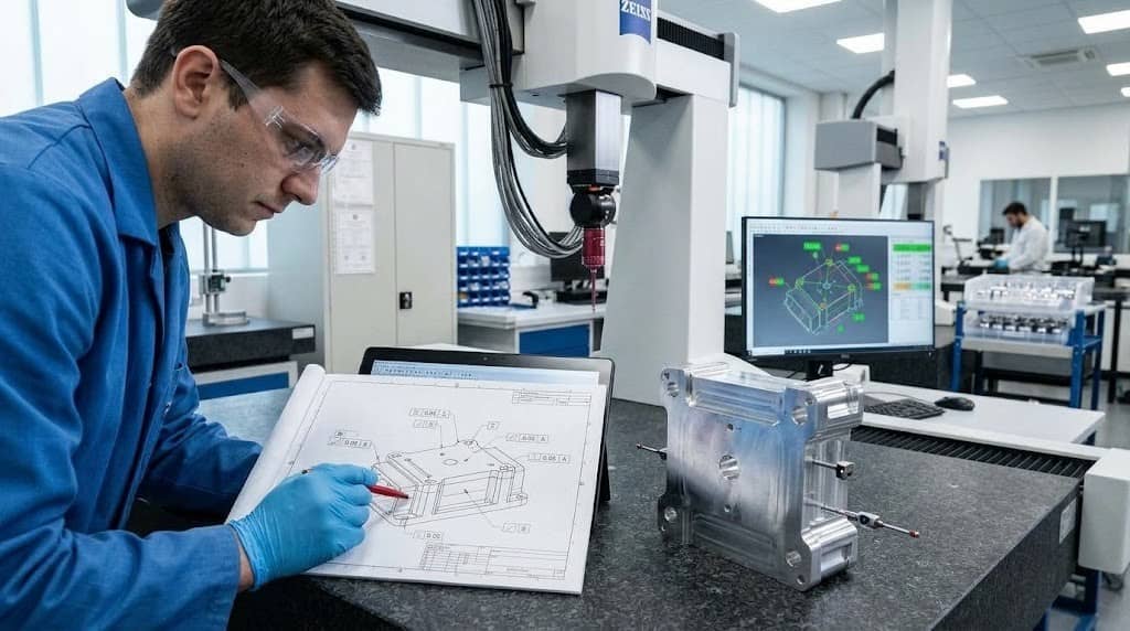
A GD&T Checklist for CNC Machined Components
Before releasing a drawing for quotation or production, please check the following:
- Critical mating features and assembly relationships are determined.
- Datums describe how the part will be located and used.
- Position tolerances govern the required locations of features.
- Surface form is specified by flatness.
- Perpendicularity is used to identify the datum and controlled feature.
- Functional requirements and manufacturing feasibility match tolerances.
- The specified requirements can be verified by means of inspection methods.
- Material, surface finish and final inspection conditions are well defined.
If you are dealing with rotating or cylindrical parts, be sure to review the manufacturing requirements associated with it along with JTR’s CNC turning guide. For more technical study, the ASME introduction to GD&T covers datum systems, form controls, orientation, and position tolerance.
Most asked questions
Q1: What is the difference between GD&T and dimensional tolerance?
Dimensional tolerances govern allowable variation in size or distance. GD&T defines allowable geometric variation, including form, orientation and location of features.
Q2. Is a datum needed for flatness tolerance?
No. Flatness is a form control and does not need a datum reference.
Q3. When would you use position tolerance instead of coordinate dimensions?
Position tolerance is useful when the location of holes or other features relative to functional datums is critical for assembly. Basic dimensions and the applicable feature control frame establish the intended location and permissible variation.
Q4: Can CNC machining achieve tight GD&T tolerances?
It depends on the material, the geometry of the part, the size of the feature, the machining process, the fixturing, and the inspection method. The required tolerance should be determined from the actual part drawing rather than from some assumed general machine accuracy.