
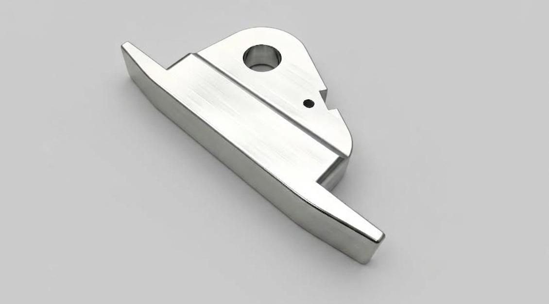
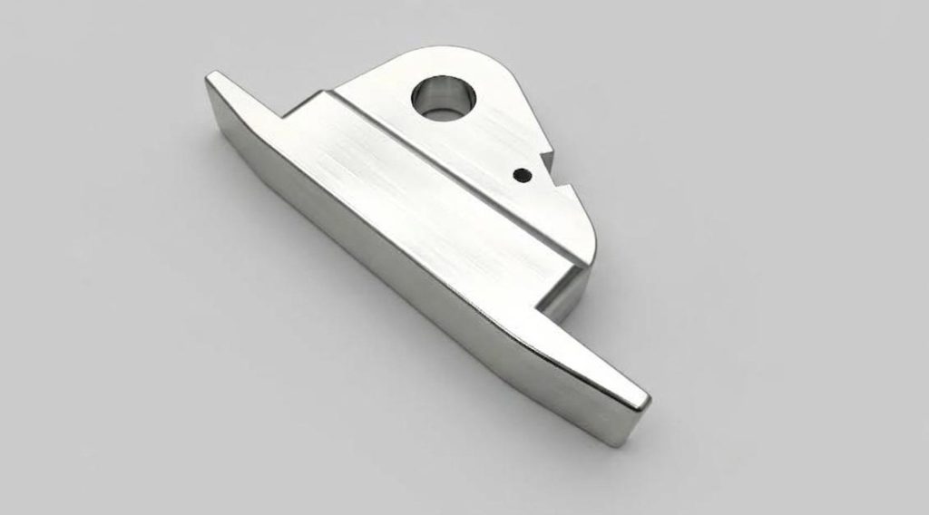
CNC Machined Aluminum Custom Swing Part
- Material: AL 6061-T6
- Size: 31*203*99
- Process: CNC Machining
- Surface treatment: Clear Anodizing
This is a custom non-standard aluminum swing cam block, machined in one piece by CNC milling. Starting from a cut-to-size aluminum billet, the process covers milling the irregular outer profile, step slots, and multi-angle chamfered faces in a single setup, followed by precision boring of the pivot assembly hole and drilling of the locating pin holes. The part is deburred after machining and finished with clear anodizing.
Machining Challenges
The difficulties here come from two directions — structural and geometric — and they tend to compound each other.
Cantilevered thin-wall structure prone to chatter and distortion. The cantilever section of this part has limited wall thickness, which means reduced rigidity under cutting forces. When the tool reaches the unsupported end, even moderate cutting loads can cause the workpiece to flex slightly — the classic chatter condition. At best, this degrades surface finish; at worst, it pushes dimensions outside tolerance and allows residual cutting stress to accumulate as minor distortion in the cantilever.
Multi-angle chamfered faces and sharp-corner profiles make fixturing difficult. The irregular geometry includes multiple oblique surfaces and sharp angles with no convenient flat face to use as a standard clamping datum. Machining different angular features requires repositioning the workpiece, and every repositioning is a potential source of positional inconsistency that feeds through to the final part accuracy.
Positional accuracy and bore finish on both large and small holes. The pivot assembly hole needs to hit its position and deliver a clean bore surface — both directly affect the kinematic accuracy and service life of whatever mechanism this part drives. The small locating holes carry their own tight positional requirements. Achieving both simultaneously on a cantilevered structure requires a deliberate machining strategy rather than a straightforward sequential approach.
How It’s Managed
| Stage | Approach |
| Fixturing | Tooling clamp plates used to secure the thin-wall cantilever section and suppress vibration throughout the cutting process |
| Roughing allowance | 0.15–0.2 mm left on all surfaces after rough milling, keeping rough-cut forces away from the final dimensional envelope |
| Finish milling parameters | Reduced feed rate and cutting speed, with layered passes — lighter cuts per pass reduce the force acting on the thin walls |
| Pivot hole boring | Dedicated finish boring operation for the pivot assembly hole, achieving the required bore diameter tolerance and interior surface finish |
| Deburring sequence | Multi-angle faces and sharp-corner profiles deburred in a staged sequence, preventing burrs from damaging mating surfaces in subsequent assembly steps |