CNC Machined POM Four-Jaw Coupling Hub
- Material: Black POM
- Size: Ø45.8X14 mm
- Process: CNC Machining
- Surface treatment: None
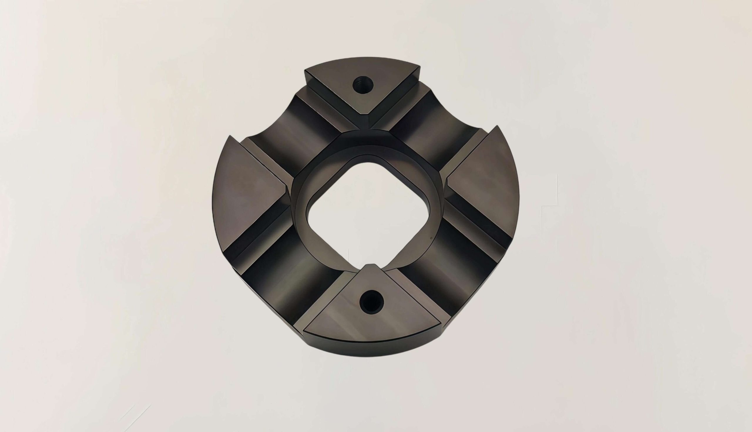
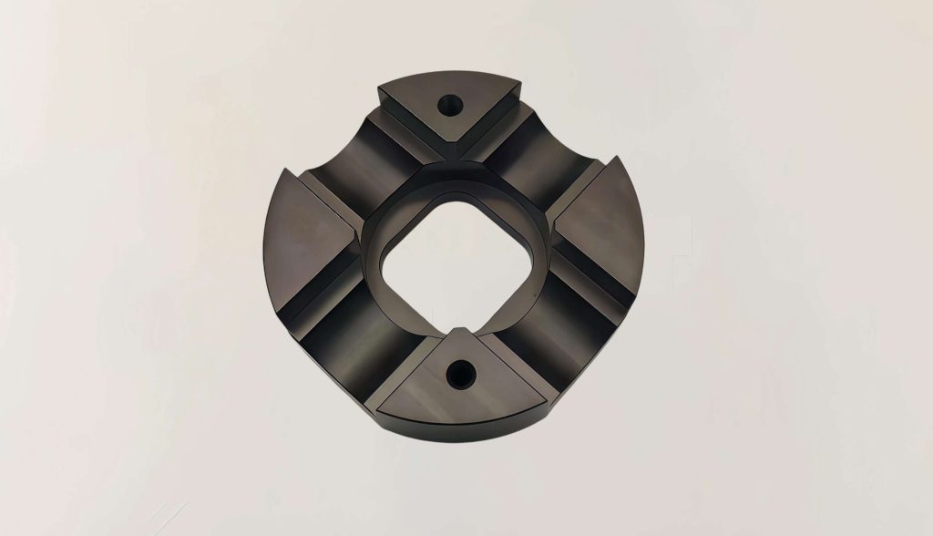
This is a four-jaw coupling hub made of POM (polyoxymethylene, also known as acetal or Delrin), machined in one piece on a CNC machine. It is one half of a jaw-type flexible coupling and works together with an elastomeric spider (the “star” insert that sits between the two hubs).
The hub is a round disc with four evenly spaced curved jaws, and each jaw tip has a bolt mounting hole. The center bore is square, so it fits a square shaft directly. No keyway or parallel key is needed, yet it still transmits torque reliably and helps prevent slipping.
POM is naturally self-lubricating, low in friction, wear resistant, and absorbs very little moisture. The finished part has a matte black surface. In operation, the four jaws grip the elastomer spider, which dampens vibration and absorbs shock, and also compensates for small shaft misalignment.
This type of coupling suits light-load, low-to-medium speed, low-noise drives that may see mild corrosive exposure. You will often find it in automation equipment, pumps, and small gear reducers. Compared with a metal coupling, it is lighter and runs more quietly.
Machining Challenges
POM machines easily, but it is not forgiving, and several issues come up on this part:
Poor thermal conductivity leads to heat buildup and melting. Cutting heat cannot escape, so the material near the cutting edge softens locally and can smear onto the tool. Once the part cools, it may also shrink and distort.
Residual stress causes slow distortion. Stress comes from both the raw stock and the cutting process, so the part can keep moving after machining and drift out of geometric tolerance.
Square bore corners are hard to clean out. The internal corners of a square bore are difficult to machine sharp, and the material springs back after cutting, which makes geometric tolerances harder to hold.
Soft material makes clamping and drilling risky. Slightly too much clamping force will deform the part, and drilling tends to cause chipping at the hole exit.
Cutting pressure creates stress whitening and burrs. Both defects can become crack initiation points once the part is under load.
How It’s Managed
| Issue | Approach |
| Heat buildup and melting | Sharp, large-rake polished end mills; air cooling; high spindle speed with a shallow depth of cut to keep cutting heat under control |
| Residual stress and distortion | Blanks annealed beforehand; symmetrical toolpaths to balance stress release |
| Square bore corners and springback | Corner relief radii added at the bore corners; spring-back allowance left for finish passes, and climb milling used |
| Clamping distortion and hole exit chipping | Vacuum chuck fixturing preferred; backing plate used when drilling, with a peck drilling cycle |
| Stress whitening and burrs | Tool edge geometry optimized to reduce material squeezing; gentle deburring methods used to avoid stress whitening |