

In modern high-precision manufacturing, choosing the correct production method is the defining factor between operational efficiency and costly downtime. Computer Numerical Control (CNC) technology has completely revolutionized the industrial landscape by replacing manual control with automated, software-driven execution. However, because modern part designs present extreme geometric complexities and highly stringent tolerances, the industry has branched into an extensive array of specialized machinery. Why are there so many different CNC machine types? The answer lies in the diversity of production requirements: machining a rotational aerospace shaft requires radically different kinematics, force vectors, and tooling than cutting a delicate medical bone plate or profiling heavy structural steel. To assist engineers, procurement professionals, and manufacturers in navigating this sophisticated landscape, this comprehensive guide breaks down every major CNC machine type, architectural axis configuration, motion control paradigm, and industrial system application, serving as the ultimate decision-making framework for your next manufacturing project.
What Is a CNC Machine?
A CNC machine is an automated manufacturing device that utilizes pre-programmed sequences of computer commands to control the movement of factory tools and machinery. Unlike manual machining, where operators physically manipulate handwheels and levers, a CNC system converts a digital design into precise physical movements along multiple geometric axes. The workflow begins with Computer-Aided Design (CAD) software, where engineers generate a 3D digital model of the intended component. This digital asset is then exported into Computer-Aided Manufacturing (CAM) software, which analyzes the geometry and synthesizes the exact toolpaths required to cut the part from raw stock. The CAM software translates these paths into machine-readable alphanumeric code: G-code (which controls primary motion, coordinates, and feed rates) and M-code (which governs miscellaneous auxiliary functions such as spindle activation, coolant control, and tool changes). This code is transferred to the machine’s onboard controller, which commands high-torque motors to execute the subtractive manufacturing process with absolute precision.
Digital Design (CAD) → CAM Toolpath Programming → CNC Controller (G/M-Code) → Servo Motion Control → Finished Precision Parts
How CNC Machines Can Be Classified
To accurately evaluate and integrate these systems into a production workflow, industrial CNC machinery must be systematically categorized according to its mechanical capabilities, control logic, and motion kinematics. The following matrix outlines the fundamental classification framework utilized across the manufacturing sector:
| Classification Metric | Primary Engineering Types & Sub-categories |
| By Machining Process | Milling (VMC/HMC), Turning (Lathes/Swiss), Drilling, Grinding, EDM (Wire/Sinker), Laser, Plasma, Waterjet Cutting |
| By Motion Control Type | Point-to-Point (PTP) Positioning, Continuous Path / Contouring (Linear, Circular, and Spline Interpolation) |
| By Number of Axes | 2-Axis, 2.5-Axis, 3-Axis, 4-Axis (Indexed/Simultaneous), 5-Axis (Simultaneous Kinematics) |
| By System Control Loop | Open-Loop Systems (Stepper Motors), Closed-Loop Systems (Servo Feedback via Encoders/Linear Scales) |
| By Automation Level | Manual Loading Setup, Automatic Tool Changers (ATC), Pallet Changers, Fully Integrated Robotic Cells |
Types of CNC Machines by Machining Process
1. CNC Milling Machine
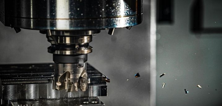
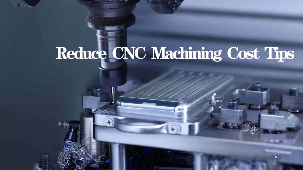
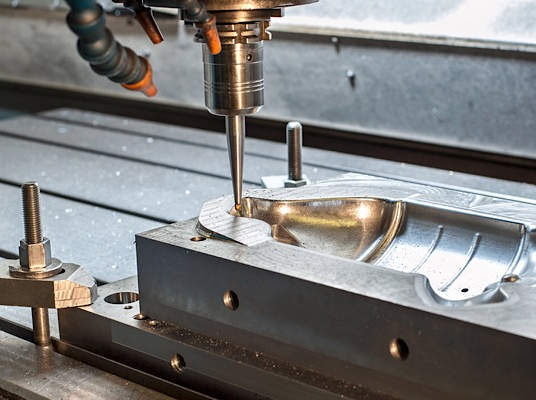
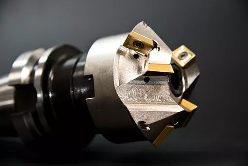
CNC milling involves securing a raw workpiece into a stationary workholding device (such as a vise or fixture) while a multi-point cutting tool rotates at high speeds against the material to remove stock via programmed toolpaths. These machines are commonly split into Vertical Machining Centers (VMC), where the spindle axis is vertical, and Horizontal Machining Centers (HMC), which feature a horizontal spindle and are optimized for heavy chip evacuation and multi-face high-volume production.
- Advantages: Exceptional geometric flexibility, high material removal rates (MRR), and capable of producing intricate 3D complex geometries.
- Disadvantages: Higher initial tooling and setup costs; complex geometries require sophisticated multi-axis programming and advanced workholding.
- Typical materials & tolerances: Aluminum (6061, 7075), Steel, Titanium, Plastics (PEEK, Delrin). Achieves standard dimensional tolerances of ±0.005 mm (±0.0002 inches).
- Applications & Industries: Structural aerospace brackets, automotive engine components, custom plastic enclosures, mold and die manufacturing.
- Suitable parts: Prismatic parts, valve bodies, manifolds, housings, and pocketed structural plates.
2. CNC Turning Machine (Lathes & Turning Centers)
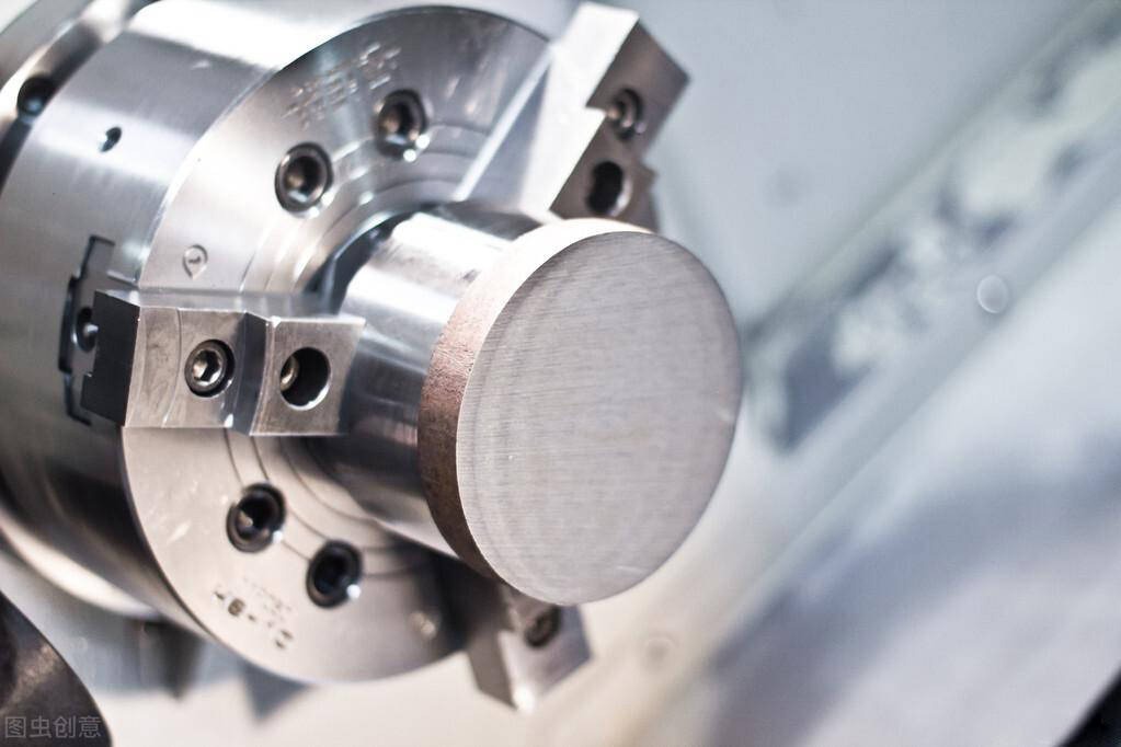
Unlike milling, CNC turning rotates the workpiece at high speeds within a chuck while a single-point cutting tool remains stationary, moving linearly along the X and Z axes to shear away material. Modern CNC Turning Centers frequently feature live tooling, allowing rotational parts to undergo secondary milling, cross-drilling, and tapping operations without leaving the lathe. For ultra-precise, long, and slender micro-components, a Swiss-type CNC lathe (sliding headstock lathe) is utilized, feeding the bar stock through a guide bushing directly next to the cutting tool to eliminate material deflection.
- Advantages: Rapid cycle times, unparalleled concentricity for cylindrical parts, and highly efficient raw material utilization.
- Disadvantages: Strictly restricted to parts with a primary rotational or axis-symmetric profile; secondary features require live tooling or multi-spindle configurations.
- Typical materials & tolerances: Stainless steels (303, 316), Brass, Copper, Inconel. Precision tolerances regularly hit ±0.0025 mm.
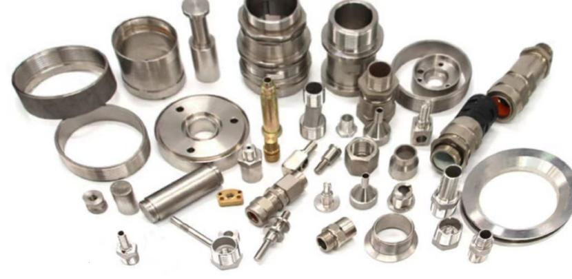
- Applications & Industries: Medical bone screws, aerospace fasteners, automotive drive shafts, hydraulic fittings, and fluid connectors.
- Suitable parts: Shafts, pins, bushings, dowels, nozzles, and complex stepped cylinders.
3. CNC Drilling Machine
Optimized specifically for generating, reaming, and tapping internal holes, these machines utilize specialized rotating drills. While standard VMCs can drill, dedicated CNC drilling systems are designed for high-speed, deep-hole penetration utilizing gun drilling techniques where high-pressure coolant is delivered internally through the drill bit to flush out micro-chips.
- Advantages: Rapid axial throughput, dedicated rigid setups, and unmatched depth-to-diameter tracking accuracy.
- Disadvantages: Geometrically limited strictly to hole-making and internal threading operations.
- Typical materials & tolerances: Heavy structural steels, cast iron, alloy steels. Hole diameter tolerances are tightly held within ±0.012 mm.
- Applications & Industries: Heat exchanger tube sheets, oil gas drill collars, structural building frameworks.
- Suitable parts: Deep-hole tubes, engine block cylinder rows, bolted pattern plates.
4. CNC Grinding Machine
CNC grinding is an abrasive machining process that utilizes a high-speed rotating abrasive wheel to achieve extreme surface finishes. It includes Surface Grinding (for flat faces), Cylindrical Grinding (for outer and inner diameters of shafts), and Centerless Grinding (where parts are supported between a regulating wheel and a grinding wheel without a chuck). It is primarily used as a secondary finishing process for pre-hardened components.
- Advantages: Capable of machining extremely hard materials; yields mirror-like surface finishes down to 0.1 Ra.
- Disadvantages: Very low material removal rates; abrasive wheels experience wear and require regular automated dressing cycles.
- Typical materials & tolerances: Hardened tool steels, tungsten carbide, industrial ceramics. Reaches tight tolerances of ±0.001 mm.
- Applications & Industries: Aerospace bearing raceways, precision gauge blocks, high-pressure hydraulic pistons.
- Suitable parts: Valve spools, fuel injector pins, precision shafts, and tooling dies.
5. CNC EDM Machine (Electrical Discharge Machining)
EDM is a non-traditional thermal process that removes metal by generating continuous, high-frequency spark discharges between a conductive tool and the workpiece inside a dielectric fluid. In Wire EDM, a continuously fed thin brass or zinc-coated wire acts as the electrode to slice complex 2D profiles through thick blocks. In Sinker EDM (Die Sinking), a custom-machined graphite or copper electrode is plunged into the material to burn a blind matching cavity. Micro EDM scales this process down using sub-micron electrodes for microscopic features.
- Advantages: Completely stress-free machining with zero mechanical force vectors; effortlessly cuts through extremely hard conductive metals regardless of hardness.
- Disadvantages: Restricted entirely to electrically conductive materials; process is structurally slow compared to conventional milling.
- Typical materials & tolerances: Hardened Steel, Titanium, Inconel, Carbide. Precision limits reach ±0.002 mm.
- Applications & Industries: Aerospace turbine blade root slots, medical implant micro-slots, plastic injection mold cavities.
- Suitable parts: Stamping dies, internal spline gears, ultra-thin walls, and intricate extrusion dies.
6. CNC Laser Cutting Machine
Uses a highly concentrated, computerized laser beam (typically Fiber or CO2) to melt, vaporize, or burn through flat stock materials, utilizing an assist gas (such as Nitrogen or Oxygen) to cleanly blow away the molten slag.
- Advantages: Extremely narrow kerf widths, minimal thermal distortion, rapid cutting speeds for sheet metal, and no physical tool wear.
- Disadvantages: Restricted primarily to thin sheet materials; thick sections create taper errors and heat-affected zones (HAZ).
- Typical materials & tolerances: Carbon steel, Stainless Steel, Aluminum, Brass. Positional accuracy is typically ±0.05 mm.
- Applications & Industries: Automotive chassis panels, electronics enclosures, sheet metal brackets, signage.
- Suitable parts: Flanges, flat structural plates, shims, sheet metal blanks.
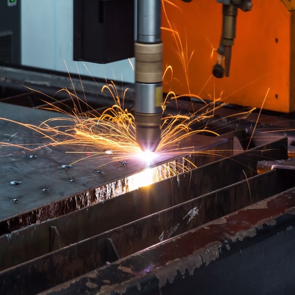
7. CNC Plasma Cutting Machine
Directs an accelerated jet of hot, electrically ionized plasma gas through a nozzle directly onto a conductive material, melting and blowing the metal away to create rapid profiles.
- Advantages: High cutting speeds on thick, heavy plates; significantly lower equipment capital cost compared to large lasers.
- Disadvantages: Creates a wider kerf and noticeable edge taper; leaves a substantial heat-affected zone requiring post-processing.
- Typical materials & tolerances: Structural Carbon Steel, Heavy Stainless Steel. Cut tolerances range within ±0.5 mm to ±1.0 mm.
- Applications & Industries: Shipbuilding, heavy industrial construction, steel fabrication shops.
- Suitable parts: Structural gussets, heavy base plates, structural steel beam profiles.
8. CNC Waterjet Machine
Projects an ultra-high pressure stream of water—up to 60,000 to 90,000 PSI—mixed with a granular abrasive material (typically garnet) through a diamond nozzle to mechanically erode a thin path through raw stock.
- Advantages: True cold cutting process with zero heat-affected zones (HAZ); can cut virtually any material including composites and non-metals.
- Disadvantages: Slower processing speeds on thick hard materials; operating costs for abrasive consumption are high; potential for edge taper on deep cuts.
- Typical materials & tolerances: Titanium, Carbon Fiber Composites, Glass, Stone, Copper. Achieves tolerances of ±0.1 mm.
- Applications & Industries: Aerospace carbon fiber panels, architectural stone structures, gasket fabrication.
- Suitable parts: Interlocking composite flat plates, thick titanium raw blanks, industrial glass panels.
CNC Machines by Number of Axes
The kinematic capability of a CNC machine is dictated by its total number of independent motion axes. Selecting the appropriate axis configuration directly determines part cost, cycle time, surface quality, and setup complexity.
| Axis Class | Kinematic & Motion Capability | Geometric Complexity | Relative Capital Cost | Primary Engineering Applications |
| 2 Axis | Simultaneous movement in 2 axes (typically X and Z on standard lathes). | Low (Symmetric / Rotational) | Low ($) | Simple shafts, pins, sleeves, and basic turned bushings. |
| 2.5 Axis | Movement in 3 axes, but interpolation only occurs simultaneously in 2 axes (Z steps down). | Medium-Low (Planar) | Low-Medium ($$) | Flat plates with drilled hole patterns, shallow linear pockets, and brackets. |
| 3 Axis | Full simultaneous interpolation across X, Y, and Z spatial dimensions. | Medium (True 3D Surfaces) | Medium ($$$) | Manifolds, standard engine components, mold cavities, mechanical fixtures. |
| 4 Axis | 3 Linear axes plus 1 Rotary axis (A-axis around X, or B-axis around Y). | High (Wrapped / Indexed) | High ($$$$) | Camshafts, helical gears, multi-sided prismatic transmission housings. |
| 5 Axis | 3 Linear axes plus 2 Rotary axes (A, B, or C) performing full simultaneous kinematics. | Very High (Complex Organic) | Highest ($$$$$) | Aerospace impellers, turbine blades, complex anatomical medical implants. |
1. 2-Axis CNC Machine
Standard 2-axis CNC configurations are found in baseline CNC lathes. Movement is mapped along the Z-axis (longitudinal travel parallel to the spindle center) and the X-axis (radial cross-slide travel defining the diameter). It is highly optimized for rotational symmetry. Its main advantage is mechanical simplicity, offering rapid indexing, low maintenance, and highly cost-effective high-volume production. However, it is fundamentally limited, as any off-axis features (such as cross-drilled holes, flat faces, or keyways) cannot be machined, requiring manual intervention or separate transfer to a milling machine.
2. 2.5-Axis CNC Machine
A 2.5-axis system possesses three physical axes (X, Y, and Z), but the controller cannot interpolate all three axes simultaneously. The system performs full 2D interpolation along the X-Y plane, while the Z-axis acts as an incremental step-down control. Once the Z-axis reaches its designated depth layer, it locks in place while the cutting tool executes the 2D contouring pass. While highly effective for simple pockets, step-downs, and surface face milling, it is unable to produce smooth, organically curved 3D surfaces. Attempting to machine a complex 3D contour on a 2.5-axis system results in pronounced “stair-stepping” artifacts that require extensive manual post-finishing.
3. 3-Axis CNC Machine
The 3-axis configuration represents the foundational bedrock of conventional industrial machining. The tool moves simultaneously through three linear dimensions: the X-axis (left-to-right), Y-axis (front-to-back), and Z-axis (up-and-down). This allows full simultaneous spatial toolpaths, making it capable of machining smooth, complex 3D profiles, mold cavities, and contoured surfaces. It offers an exceptional balance of mechanical rigidity, programming simplicity, and cost-effective operation. Its main limitation is geometric line-of-sight: because the tool remains perpendicular to the machine bed, undercut features, internal cavities, and features angled on multiple planes cannot be reached without physically stopping the machine, creating custom workholding fixtures, and re-orienting the workpiece for subsequent setups.
4. 4-Axis CNC Machine
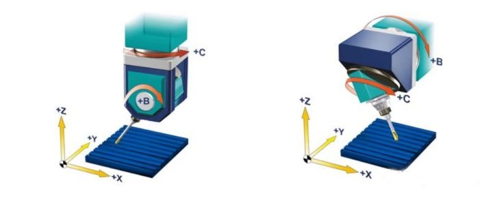
A 4-axis machine incorporates the traditional three linear axes plus a single rotary axis, typically designated as the A-axis (rotation around the X-axis) or the B-axis (rotation around the Y-axis). This rotary movement is achieved via an integrated rotary table or an indexing trunnion unit. 4-axis machining can be run in two modes: Indexed 4-axis (4-axis positioning), where the rotary axis spins the part to a specific angular orientation and locks it in place while the 3 linear axes execute the cut; and Simultaneous 4-axis machining, where the rotary axis turns continuously at the same time the linear axes move. This system significantly reduces setup operations, improves accuracy by maintaining a single datum reference, and allows efficient machining of wrapped geometries such as cylindrical cams, continuous scroll paths, and helical gear teeth.
5. 5-Axis CNC Machine
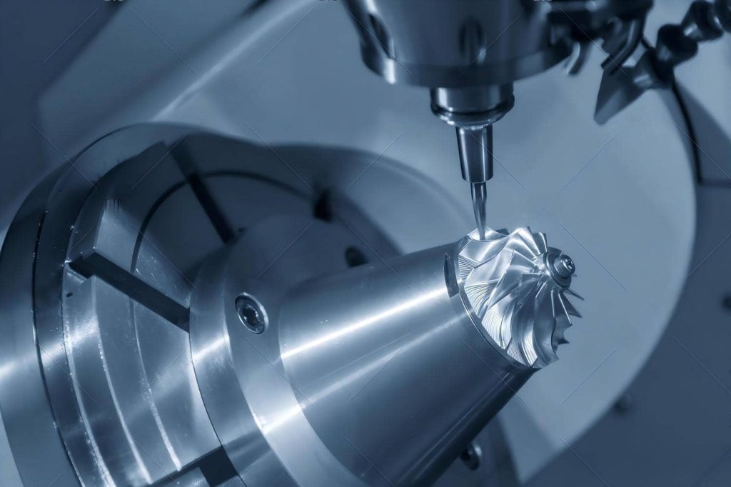
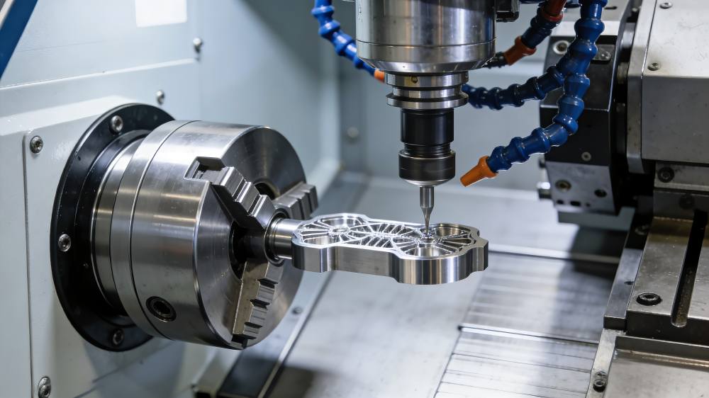
The pinnacle of subtractive manufacturing kinematics is the Simultaneous 5-axis CNC machine. This architecture utilizes the three standard linear dimensions (X, Y, Z) coupled with two independent rotational axes selected from the A-axis (rotation around X), B-axis (rotation around Y), or C-axis (rotation around Z). These rotary motions are mechanically integrated either through a Trunnion Table configuration (where the table tilts and rotates) or a Swivel Head / Articulated Spindle design (where the spindle itself changes its angular orientation).
To execute these highly sophisticated continuous toolpaths without collision, advanced 5-axis controllers utilize RTCP (Rotary Tool Center Point) tracking. RTCP ensures that the CNC controller automatically compensates for the changing spatial coordinates of the tool tip as the rotary axes articulate, keeping the tool perfectly relative to the workpiece. 5-axis machining delivers massive manufacturing benefits: it completely eliminates multi-setup errors by enabling Done-in-One (single-setup) machining, allows shorter, more rigid cutting tools to be used by tilting the spindle to prevent tool deflection, and provides access to complex undercuts and deep organic draft angles. It is the mandatory industrial standard for producing critical components such as monolithic aerospace impellers, scimitar turbine blades, multi-port automotive cylinder heads, and custom anatomical medical joint replacements.
CNC Machine Types by Motion Control
Beyond structural axis configuration, CNC controllers are fundamentally differentiated by their motion tracking logic and interpolation intelligence. The system’s operation determines whether it functions as a point-to-point positioning device or a continuous contouring machine.
Point-to-Point (PTP) CNC Systems
In a Point-to-Point (PTP) CNC system, the machine’s primary function is to move the cutting tool rapidly to a specific, pre-programmed coordinate position without controlling the exact path taken during the transition between points. The cutting tool remains retracted and non-operational while rapid positioning travel takes place. The drive motors maximize acceleration and velocity to reach the target coordinate, and once the position is secured and verified, the machining operation (such as drilling, tapping, or punching) occurs along a single axis. Typical examples include dedicated CNC drilling machines, automated spot-welding systems, and turret punch presses. While highly efficient for pattern-based operations, PTP systems are completely incapable of profiling edges or generating complex surface transitions.
Continuous Path (Contouring) CNC Systems
Continuous Path or Contouring CNC systems maintain precise control over the velocity, position, and acceleration vectors of multiple axes simultaneously while the cutting tool is actively engaged with the material. This continuous spatial orchestration requires the controller to calculate millions of micro-positions per second using sophisticated real-time interpolation algorithms:
- Linear Interpolation: The controller coordinates multiple axes to move in a perfectly straight line between two spatial coordinates at a designated feed rate.
- Circular Interpolation: The controller synchronizes two or more linear axes to execute true arc profiles and cylindrical paths.
- Spline Interpolation (NURBS): Advanced mathematical algorithms that enable the controller to execute smooth, organic curves through a cloud of data points, minimizing jerk and tool vibration.
Continuous path control is the critical technology behind high-speed VMCs, complex turning centers, and multi-axis mill-turn machines. It is the absolute prerequisite for manufacturing complex aerodynamic profiles, advanced automotive stamping dies, intricate aerospace structural components, and anatomical medical implants.
Open-Loop vs. Closed-Loop CNC Systems
The positioning accuracy and industrial reliability of a CNC machine depend heavily on whether its electronic drive architecture operates as an open-loop or closed-loop feedback network.
| Functional Feature | Open-Loop CNC Architecture | Closed-Loop CNC Architecture |
| Feedback Mechanism | None. No monitoring of physical position. | Continuous. Real-time monitoring of axis locations. |
| Primary Motor Technology | Digital Stepper Motors | High-Torque AC/DC Servo Motors |
| Positioning Accuracy | Medium. Vulnerable to lost steps under heavy load. | Ultra-High. Real-time positional auto-correction. |
| System Cost Structure | Highly Cost-Effective ($) | Significant Capital Investment ($$$) |
| Maximum Operational Speed | Moderate. Rapid acceleration can cause stalling. | High. Rapid acceleration with precise control. |
| Industrial Application Fit | Hobbyist, desktop routers, light prototyping. | Industrial manufacturing, multi-axis machining. |
Open-Loop Systems
An open-loop CNC system sends digital step signals from the main controller to a stepper motor driver, directing the motor to rotate a specific number of degrees to translate into linear movement via a ballscrew. The defining characteristic of an open-loop system is that there is no feedback device to verify whether the motor actually executed the movement command. The controller operates on blind trust. If the cutting force exceeds the motor’s torque capacity, or if a mechanical jam occurs, the stepper motor will “lose steps.” The controller remains unaware of this positioning error, and the machine will continue executing subsequent lines of G-code at an incorrect offset, ruining the workpiece and potentially causing a severe tool crash.
Closed-Loop Systems
An industrial-grade closed-loop CNC system incorporates a continuous real-time feedback loop. The drive architecture utilizes high-performance servo motors coupled with precision optical measuring hardware: Rotary Encoders mounted to the rear of the motor shaft monitor rotational displacement, while ultra-precise Linear Scales mounted directly to the machine axes track the actual physical position of the machine table down to the sub-micron level. This tracking data is fed continuously back to the CNC controller’s comparator circuit. If a physical tracking error occurs due to heavy material resistance, thermal expansion, or mechanical backlash, the controller calculates the difference between the programmed position and the actual position. It applies instant dynamic position compensation, boosting current to the servo motors to correct the tracking error in milliseconds. Closed-loop architecture ensures absolute accuracy, eliminates lost steps under heavy structural loads, and is mandatory for all high-volume, high-precision industrial manufacturing operations.
CNC Machines by Industry
Different industry sectors impose specific regulatory, material, and geometric requirements on manufacturing, driving the adoption of specialized CNC machinery setups:
- Aerospace Industry: Demands the machining of tough, high-strength superalloys such as Titanium and Inconel, alongside large monolithic aluminum structural parts. This sector relies heavily on high-rigidity 5-axis simultaneous VMCs and large-scale Gantry CNC mills to produce lightweight structural ribs, engine impellers, and turbine casings with thin walls and complex internal angles.
- Medical Device Manufacturing: Characterized by microscopic components, exceptional surface finishes, and bio-compatible materials like Titanium, Cobalt-Chrome, and PEEK. The dominant machinery types are multi-axis Swiss-type CNC Lathes and Micro-EDM systems, which are highly optimized for producing bone screws, orthopedic joint replacements, pacemaker housings, and custom surgical instruments.
- Automotive Mass Production: Prioritizes rapid cycle times, high structural reliability, and low cost-per-part metrics. This sector utilizes automated cells of Horizontal Machining Centers (HMCs) with multi-pallet changers, alongside multi-spindle CNC Turning Centers to process engine blocks, transmission cases, brake calipers, and drive axles.
- Electronics & Semiconductors: Requires ultra-fast processing speeds, highly precise small-diameter hole creation, and scratch-free handling of materials like copper, aluminum, and technical ceramics. It heavily deploys high-speed CNC Drilling and Tapping Centers, along with specialized optical linear-motor milling machines to fabricate intricate heat sinks, RF connectors, and semiconductor test sockets.
- Energy, Oil & Gas Sector: Characterized by massive, long, and exceptionally heavy workpieces that must withstand extreme torque and corrosive environments. This sector requires massive Heavy-Duty Vertical Boring Mills, large Swing Lathes, and deep-hole Gun Drilling rigs to machine oilfield drill pipes, large industrial subsea valves, wind turbine hubs, and nuclear reactor casing components.
How to Choose the Right CNC Machine
To accurately select the ideal CNC machine setup for a specific project, engineers must follow a structured, logical evaluation matrix that prevents over-specifying equipment (which inflates production costs) or under-specifying (which leads to scrap parts and mechanical failures).
1. Assess Material Hardness & Thermal Sensitivity → 2. Define Part Geometries & Undercut Requirements → 3. Verify Stringent Tolerances & Surface Finishes → 4. Determine Production Volumes & Lead Times → 5. Evaluate Machine Capital Cost vs. Component Margins
Project Requirements Decision Matrix
| Primary Project Requirement | Ideal Machinery Selection | Engineering Justification |
| Low-Volume Prismatic Prototypes | 3-Axis Vertical Milling Center (VMC) | Highly cost-effective setup; simple programming; excellent versatility for basic geometries. |
| Complex Organic Aerospace & Medical Components | Simultaneous 5-Axis VMC / Mill-Turn | Enables Done-in-One single-setup machining; access to complex undercuts; eliminates setup alignment errors. |
| Large-Scale, Thick Structural Flat Plates | Gantry CNC Mill / Heavy Waterjet | Extensive physical envelope; high structural support; cold cutting eliminates thermal warping. |
| Axis-Symmetric, High-Volume Rotational Parts | CNC Turning Center / Swiss Lathe | Maximizes concentricity; rapid cycle times; sliding headstock prevents micro-deflection on slender rods. |
| Ultra-Hard Conductive Metals (Pre-Hardened Dies) | CNC Wire or Sinker EDM | Completely force-free spark erosion; cuts hard metals cleanly regardless of hardness without tool wear. |
| High-Precision Mirror Finishes (< 0.2 Ra) | CNC Cylindrical or Surface Grinder | Micro-abrasive machining removes minimal stock while eliminating tool marks to achieve sub-micron accuracy. |
Common CNC Machine Comparison
The following evaluation provides a final, high-level comparative analysis of the primary industrial CNC options, assessing their technical precision, cost metrics, throughput velocity, and geometric strengths:
| CNC Machine Class | Technical Accuracy | Capital Cost Metric | Throughput Velocity | Best Suited Component Profiles |
| CNC Milling | ★★★★★ | $$$ | ★★★★ | Prismatic blocks, brackets, housings, and custom 3D profiles. |
| CNC Lathe / Turning | ★★★★★ | $$ | ★★★★★ | Cylindrical shafts, precision fittings, pins, and custom fasteners. |
| CNC EDM (Wire/Sinker) | ★★★★★★ | $$$$ | ★ | Pre-hardened tool steels, thin-walled slots, and injection mold cavities. |
| CNC Grinding | ★★★★★★ | $$$ | ★★ | Secondary finishing for bearing journals, spools, and gauge faces. |
| CNC Laser Cutting | ★★★★ | $$ | ★★★★★ | Rapid profiles in sheet metal, electronic panels, and flat brackets. |
| CNC Waterjet | ★★★ | $$$ | ★★★ | Thick composite panels, titanium blanks, industrial stone, and glass. |