
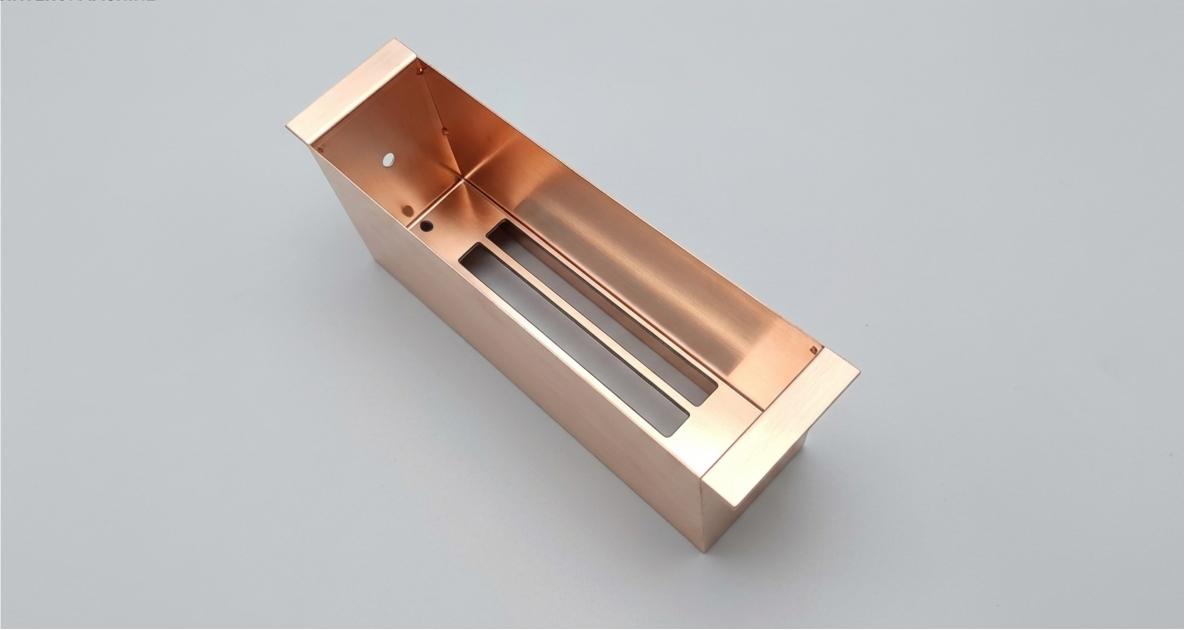
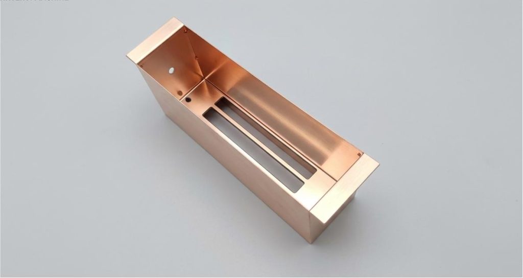
Pure Copper Thin-Wall Cavity Part
- Material: Pure Copper
- Size: 277*159*0.5
- Process: Laser Cutting + Bending + Welding
- Surface treatment: None
This is a thin-wall copper cavity part produced through three sequential processes: laser cutting, press brake bending, and welding. A 0.5 mm copper sheet is laser cut into the developed flat pattern, with all holes and slots cut at the same time. The flat blank is then CNC bent into the cavity shape and welded to close the edges. The part is deburred after welding with no additional surface treatment.
Machining Challenges
Each of the three processes carries its own difficulty, and the errors from one stage carry forward into the next — creating a compound accuracy challenge across the complete production sequence.
Laser cutting 0.5 mm sheet produces edge burning and distortion that’s hard to avoid. Copper’s exceptional thermal conductivity means heat spreads rapidly across the sheet during cutting. That fast heat diffusion causes the cut edge to overheat — resulting in edge discolouration, surface roughening, and micro-warping. A 0.5 mm sheet has almost no inherent stiffness to resist thermal distortion; if the blank comes off the laser anything other than flat, the bending process that follows loses its dimensional reference from the start.
Copper’s softness makes it easy to mark and difficult to bend accurately. Copper is soft enough that any roughness or debris on the die contact surface will leave impressions or scratches on a 0.5 mm blank. The springback behaviour of copper is also different from aluminium or steel — larger in magnitude and less predictable at this thickness. Compensation values can’t be taken from standard tables; they have to be established by trial bends specific to this material and gauge, then verified before production runs.
Thin-wall welding demands extremely precise heat control to avoid burn-through. At 0.5 mm wall thickness, any excess in welding current or heat input produces a hole almost instantly. Copper’s high thermal conductivity accelerates heat transfer into the surrounding area, which raises the temperature of the weld zone faster than with most other metals and increases the burn-through window accordingly. Producing 40 parts with consistent weld quality adds another layer of complexity — every joint across the full batch needs to be made under the same controlled conditions, with no missed or weak welds.
How It’s Managed
| Stage | Approach |
| Laser cutting parameters | Power, speed, and assist gas pressure optimised specifically for 0.5 mm copper to minimise the heat-affected zone and reduce edge burning and thermal distortion |
| Soft tooling for bending | Soft dies (polyurethane pads) used in place of hard tooling to prevent die contact marks and impressions on the thin copper surface |
| Springback compensation | Trial bends used to establish copper-specific compensation values at 0.5 mm gauge — standard compensation tables not used |
| Low-heat precision welding | Micro-plasma or precision TIG welding with tightly controlled current and wire feed, maintaining the heat input low enough to seal the joint without burning through |
| Post-weld correction | Full straightening and correction pass after welding to remove thermal distortion and bring overall dimensions within ±0.1 mm |
| Batch process consistency | Standardized welding parameter sheets established and applied uniformly across all 40 parts, reducing inter-part variation in weld quality |