


CNC machining wall thickness is one of the most important DFM considerations when designing pockets, housings, brackets, ribs, and other machined components. A wall that is too thin may deflect, vibrate, deform during clamping, or fail to hold the required dimensional tolerance. However, there is no single minimum wall thickness that applies to every CNC machined part.
The practical limit depends on the material, wall height, geometry, tool diameter, cutting forces, workholding method, machining strategy, tolerance, and surface-finish requirements. General CNC design guidelines commonly recommend approximately 0.8 mm for metal walls and 1.5 mm for plastic walls, while thinner values may be technically feasible in carefully controlled geometries. These numbers should therefore be treated as starting points rather than guaranteed production limits.
For engineers, the better question is not simply “How thin can CNC machining go?” but rather “What wall thickness provides sufficient stiffness and dimensional stability for this specific part?”
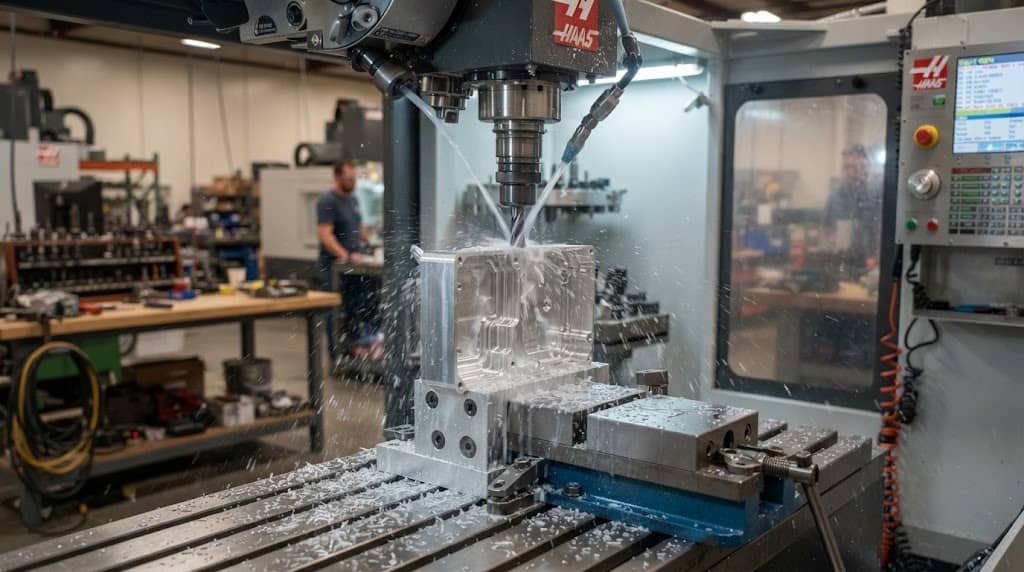
What Is Wall Thickness in CNC Machining?
Wall thickness is the minimum distance between two opposing surfaces of a machined feature. In CNC milling, it is commonly associated with the walls surrounding pockets, cavities, slots, holes, or lightweight structural sections. Thin walls appear frequently in:
- Electronic housings and enclosures
- Aerospace structural components
- Automotive brackets
- Medical components
- Optical mounts
- Heat sinks
- Lightweight aluminum parts
- Plastic housings and functional prototypes
A wall may be physically machinable at a particular thickness but still be unsuitable for production. This distinction is important because feasible minimum thickness and recommended design thickness are not the same thing.
For example, some CNC DFM guidelines identify approximately 0.5 mm as a feasible minimum for certain metal geometries and 1.0 mm for some plastics, while recommending 0.8 mm and 1.5 mm respectively for more reliable manufacturing. A production design should generally prioritize the recommended range unless there is a strong functional reason to use a thinner wall.
Recommended CNC Wall Thickness by Material
The following values can be used as initial DFM reference points, not universal machining limits.
| Material | Practical Starting Thickness | Higher-Risk Range | Primary Concern |
| Aluminum | 1.0–1.5 mm | Below ~0.8–1.0 mm | Deflection and vibration |
| Carbon/alloy steel | 1.5–2.0 mm | Below ~1.2–1.5 mm | Cutting forces |
| Stainless steel | 1.5–2.5 mm | Below ~1.5 mm | Heat and work hardening |
| Engineering plastics | 2.0–3.0 mm | Below ~1.5–2.0 mm | Flexing and thermal deformation |
CNC DFM guidance commonly uses 0.8 mm as a recommended minimum for metals and 1.5 mm for plastics, with thinner values requiring case-by-case evaluation.
The reason for using a range rather than one fixed number is simple: wall thickness interacts with the rest of the part geometry. A 1.0 mm wall that is only 5 mm tall and well supported may be considerably easier to machine than a 1.5 mm wall extending 40 mm above a deep pocket.
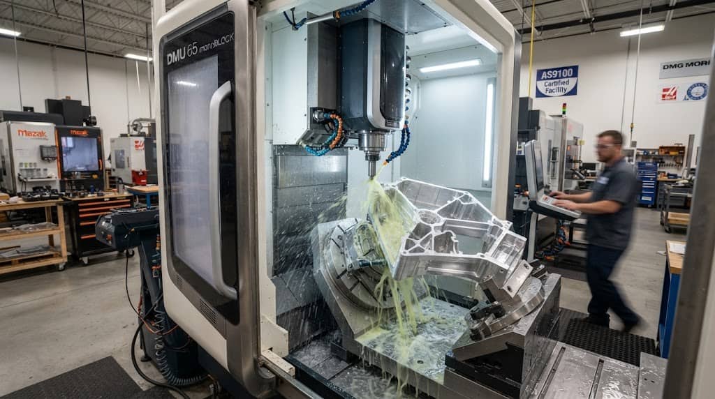
Aluminum CNC Machining Wall Thickness
Aluminum is one of the most commonly CNC machined materials because of its relatively good machinability, low density, and favorable strength-to-weight ratio. However, aluminum’s ease of cutting does not eliminate thin-wall problems.
How Thin Can Aluminum Be Machined?
For many general CNC milling applications, 1.0–1.5 mm is a sensible starting range for aluminum walls. Certain geometries can be produced below this range, but the risk of deformation and vibration increases as thickness decreases.
General DFM references identify approximately 0.5–0.8 mm as a technically feasible range for some aluminum and other metal parts, while recommending thicker walls for more reliable production. The actual result depends heavily on:
- Wall height
- Pocket depth
- Tool diameter
- Cutting direction
- Workholding
- Required tolerance
- Material temper
- Machining sequence
For example, a short 0.8 mm aluminum wall supported by surrounding material may be manageable, while a 0.8 mm wall extending deep into a cavity may deflect significantly.
Why Thin Aluminum Walls Deflect
During milling, the cutting tool applies a lateral force to the workpiece. A thin wall has relatively low bending stiffness, so it can move away from the tool. The sequence can be summarized as:
Cutting force → wall deflection → tool passes the wall → wall springs back → dimensional error
This can create several problems:
- Wall thickness outside tolerance
- Poor surface finish
- Chatter marks
- Variation between parts
- Difficulty achieving tight geometric tolerances
JTR Machine’s existing work on thin-wall aerospace aluminum machining also demonstrates why high-aspect-ratio aluminum structures require carefully sequenced machining strategies rather than simply removing material in a conventional single-pass operation.
Does 7075 Allow Thinner Walls Than 6061?
Not necessarily. 7075 aluminum has higher strength than 6061, but wall stability during machining is controlled by more than material strength. Tool pressure, geometry, elastic behavior, residual stress, wall height, and cutting parameters all affect deformation. Therefore, engineers should not automatically reduce wall thickness simply because a higher-strength aluminum alloy is being used.
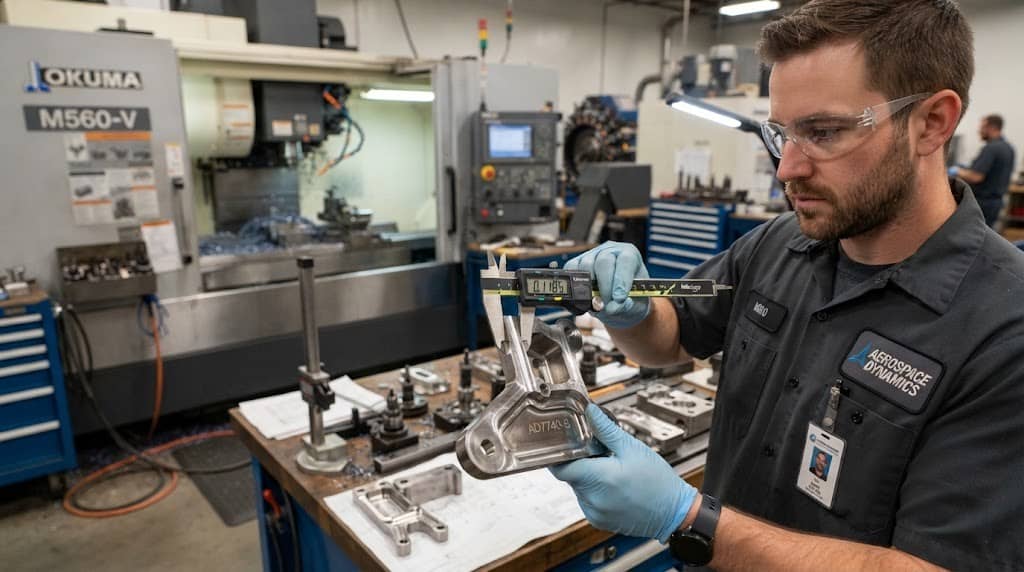
Steel CNC Machining Wall Thickness
Steel generally requires a more conservative approach to thin-wall machining than aluminum. A 1.5–2.0 mm wall is a useful starting point for many steel components, although the appropriate thickness depends on the specific steel grade and geometry.
Steel’s greater resistance to cutting can generate higher machining forces. When a thin section is exposed to these forces, the wall can deflect or vibrate even when the material itself is mechanically strong.
Why Stronger Does Not Mean Easier to Machine
A common misconception is: Stronger material = thinner wall is possible.
For CNC machining, this is not necessarily true.
The relevant issue is the interaction between: Material properties + cutting forces + geometry + workholding
A strong material can still be difficult to machine when the feature being cut has insufficient stiffness. For alloy steels, hardened steels, or other difficult-to-machine grades, the design may need additional wall thickness to maintain stability.
Stainless Steel Wall Thickness Considerations
304, 316, and other stainless steels introduce additional challenges. Stainless steel can generate significant heat during machining and may work harden when cutting conditions are not properly controlled. Thin walls make these effects more difficult to manage because there is less material available to absorb and distribute cutting forces and heat.
For many stainless steel components, 1.5–2.5 mm provides a more practical starting point than attempting to work immediately at the lower end of the feasible range. When designing thin stainless steel walls, engineers should pay particular attention to:
- Tool sharpness
- Cutting speed and feed
- Heat generation
- Work hardening
- Tool engagement
- Wall height
- Coolant strategy
- Finishing passes
If a thin stainless wall also requires a tight tolerance and fine surface finish, a DFM review becomes especially important.
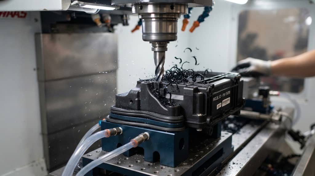
Plastic CNC Machining Wall Thickness
Plastic CNC machining requires a different approach from metal machining. Engineering plastics generally have lower stiffness and can experience greater elastic deformation and thermal expansion. Some materials can also soften as machining temperatures increase.
For this reason, plastic CNC walls are commonly designed thicker than metal walls. General CNC DFM guidance recommends approximately 1.5 mm as a minimum starting point for many plastics, while 2.0–3.0 mm can provide a more conservative design for larger or more flexible components.
Why Plastics Need Thicker Walls
A plastic wall may experience:
- Elastic deflection
- Thermal expansion
- Localized heating
- Residual-stress release
- Clamping deformation
- Tool-induced vibration
The material also matters.
POM, nylon, ABS, polycarbonate, PEEK, and other engineering plastics have different stiffness, thermal, and machining characteristics. Therefore, a single minimum thickness should not be applied to every plastic part.
For example, a short POM wall may remain stable at a thickness that would be unsuitable for a tall nylon wall. A thin PEEK component may also require a different machining strategy because of its thermal and residual-stress behavior.
Wall Height Is Just as Important as Wall Thickness
One of the most overlooked factors in CNC wall design is wall height.
Consider two walls:
- Wall A: 1.0 mm thick × 5 mm high
- Wall B: 1.0 mm thick × 40 mm high
Although their thickness is identical, Wall B is much more susceptible to bending and vibration. This is why minimum wall thickness should never be evaluated independently from the wall’s height.
A useful design concept is the height-to-thickness ratio: H/T = Wall Height ÷ Wall Thickness
As H/T increases, structural stiffness decreases and machining becomes more sensitive to cutting forces. There is no universal H/T limit that applies to every CNC operation. Published DFM guidance uses different aspect-ratio recommendations depending on the feature and manufacturing conditions. The practical design principle is therefore:
The taller the unsupported wall, the thicker it generally needs to be.
If a design contains a tall, thin wall, increasing thickness is often the simplest solution. If weight must remain low, adding ribs or intermediate supports may be more effective.
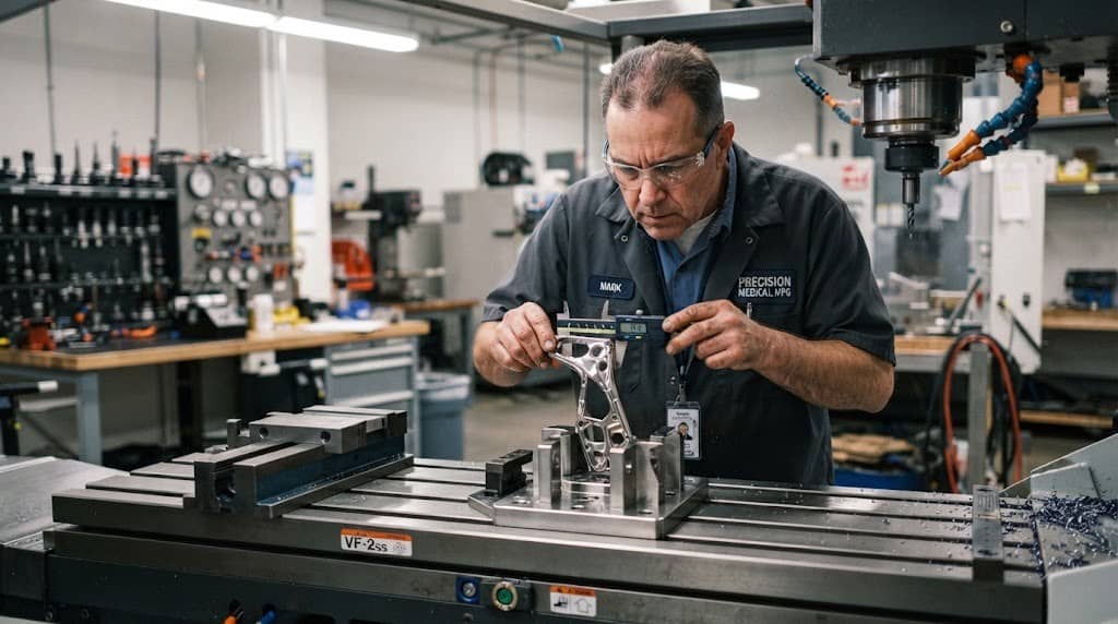
What Determines the Minimum CNC Wall Thickness?
Wall thickness should be evaluated as part of the complete machining system rather than as an isolated dimension.
1. Material
Material influences:
- Cutting forces
- Elastic deformation
- Thermal expansion
- Machinability
- Tool wear
- Residual stress
Aluminum, steel, stainless steel, and plastics therefore require different design approaches.
2. Wall Height
A thin wall becomes increasingly difficult to control as its unsupported height increases. A tall wall should generally be thickened or supported.
3. Tool Diameter and Tool Stiffness
Small-diameter tools are more susceptible to deflection and vibration. Deep features may also require tools with a high length-to-diameter ratio, which reduces tool stiffness. CNC design guidance notes that both workpiece stiffness and tool stiffness affect achievable tolerances and machining stability.
This creates an important relationship:
Deep cavity → long tool → lower tool stiffness → greater vibration risk
Therefore, a thin wall located next to a deep cavity can be much more challenging than the same wall in a shallow feature.
4. Pocket Depth
Deep pockets often create thin walls with limited support. If a deep cavity is surrounded by thin sections, the design combines several risk factors:
Thin wall + high wall height + deep pocket + long tool
This is one of the configurations that should receive particular attention during DFM review.
5. Workholding
The way the part is clamped can significantly influence thin-wall machining. Excessive clamping pressure may deform a thin component before machining begins. After the part is released, it can spring back and reveal dimensions that were different from those measured while the part was clamped.
Workholding also affects the number of setups and therefore dimensional consistency. CNC design guidance identifies workholding as an important factor in both machining cost and accuracy.
6. Machining Direction and Toolpath
Tool engagement and cutting direction influence the force acting on a thin wall. A poorly selected toolpath may continuously push the tool against a flexible wall. A more controlled strategy can reduce cutting load and improve stability.
For difficult thin-wall components, manufacturers may use:
- Roughing passes
- Semi-finishing passes
- Finishing passes
- Lower radial engagement
- Smaller axial or radial depths of cut
- Symmetrical machining sequences
The correct strategy depends on the geometry and machine setup.
7. Tolerance
A wall that is acceptable with a general dimensional tolerance may not be suitable when the drawing requires extremely tight tolerances.
For example: A 1.0 mm wall may be machinable, but maintaining a very tight tolerance on that wall may require a substantially more controlled process.
JTR Machine’s existing guidance on tolerance and surface finish also emphasizes that tighter tolerances can require additional machining passes and more controlled finishing operations.
8. Surface Finish
Thin walls are more sensitive to vibration. If the finished surface must be smooth or cosmetic, the machining strategy may need to use lighter finishing passes. This means that wall thickness cannot be separated from surface-finish requirements.
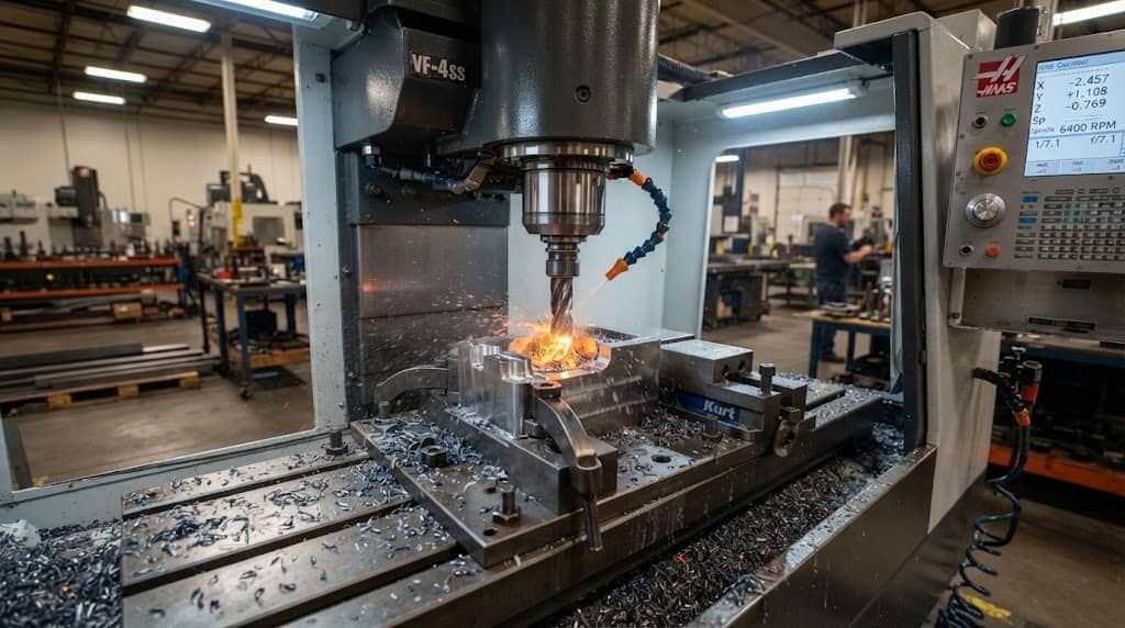
What Happens When a CNC Wall Is Too Thin?
A wall that is below a practical thickness does not necessarily fail immediately. More commonly, it introduces manufacturing instability.
- Wall Deflection: The cutting tool pushes the wall away from its programmed position.
- Chatter and Vibration: The flexible wall vibrates under cutting forces, producing visible machining marks and potentially damaging the tool or part.
- Dimensional Inaccuracy: After the cutting force disappears, the wall can spring back, leaving the final dimension different from the toolpath expectation.
- Clamping Deformation: Thin sections may be distorted by the fixture itself.
- Poor Surface Finish: Vibration during finishing passes can create uneven or wavy surfaces.
- Higher Machining Cost: Thin walls often require more conservative cutting parameters and additional finishing passes. This can increase cycle time and reduce production efficiency.
- Increased Scrap Risk: The thinner and more demanding the feature becomes, the more sensitive it is to material variation, tool wear, machine conditions, and process changes.
This is why designing the thinnest possible wall is rarely the same as designing the lowest-cost part.
How to Design Thin-Wall CNC Parts for Better Manufacturability
When a component requires thin walls, the objective should be to increase stiffness without unnecessarily increasing weight or material consumption.
1. Increase Wall Thickness Where Function Allows
This is the simplest solution. If a 1.0 mm wall can be changed to 1.5 mm without affecting the component’s function, assembly, or weight target, the design may become considerably easier to manufacture.
2. Add Ribs Instead of Making the Entire Wall Thicker
For lightweight components, ribs can provide additional stiffness without requiring a large increase in overall material volume.
This is particularly useful for:
- Aerospace components
- Automotive brackets
- Equipment housings
- Structural aluminum parts
The objective is to improve stiffness rather than simply add mass.
3. Reduce Unsupported Wall Height
If the wall is too tall, introduce supporting geometry where possible. A shorter unsupported section is generally more stable than one continuous tall wall.
4. Increase Internal Corner Radii
CNC milling tools are round, so internal corners naturally require a radius. Increasing the radius can allow the use of a larger, stiffer cutter and reduce machining difficulty. A larger internal radius can therefore improve both manufacturability and machining efficiency.
5. Reduce Pocket Depth Where Possible
A deep pocket surrounding a thin wall creates a difficult machining condition. Reducing pocket depth, adding support, or modifying the geometry can make the feature significantly more stable.
6. Use a Multi-Stage Machining Strategy
Thin-wall parts often benefit from controlled material removal rather than machining directly to the final wall thickness in one aggressive operation.
A typical strategy may involve: Roughing → Semi-finishing → Stress management if required → Finishing
The exact sequence depends on material, part size, geometry, and required tolerance.
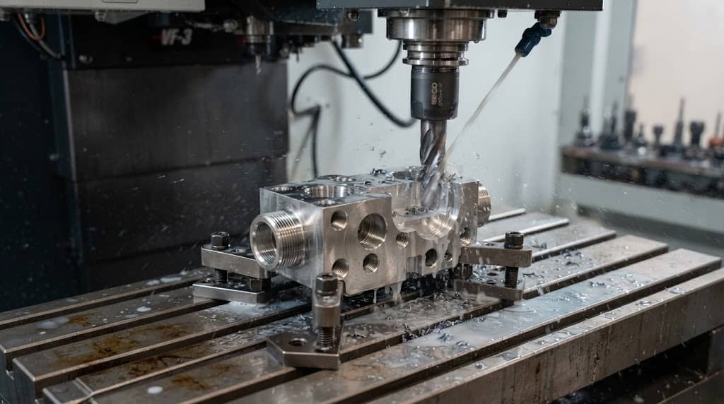
Can CNC Machining Produce Walls Thinner Than 1 mm?
Yes, in some cases. But “technically possible” does not mean “recommended for production.”
DFM guidelines identify approximately 0.5 mm as a feasible value for some metal features and around 1.0 mm for certain plastics, but they also emphasize that such features should be evaluated case by case. A sub-1 mm wall becomes more realistic when:
- The wall is short
- The geometry provides strong support
- Cutting forces can be minimized
- The material is suitable
- The fixture provides adequate support
- Tolerance requirements are moderate
- The machining sequence is optimized
- The manufacturer has experience with thin-wall components
Conversely, a sub-1 mm wall that is tall, deep inside a pocket, difficult to access, and subject to tight dimensional tolerances represents a much higher manufacturing risk.
JTR Machine’s experience with thin-wall aerospace aluminum components illustrates this distinction. Its published work describes aluminum structures with wall thicknesses below 1 mm and depths exceeding 100 mm, where dimensional control requires specialized machining strategies and stress-management techniques rather than relying on a simple minimum-thickness rule.
Minimum vs. Recommended CNC Wall Thickness: Quick Reference
The following table provides a practical starting point for early-stage design:
| Material | General Feasible Range | Recommended Starting Point | Consider Increasing Thickness When |
| Aluminum | ~0.5–0.8 mm+ | 1.0–1.5 mm | Wall is tall, deep, or tightly toleranced |
| Steel | ~0.8–1.0 mm+ | 1.5–2.0 mm | Cutting forces or tool engagement are high |
| Stainless steel | ~0.8–1.0 mm+ | 1.5–2.5 mm | Heat, work hardening, or surface finish is critical |
| Engineering plastics | ~1.0–1.5 mm+ | 2.0–3.0 mm | Part is flexible, large, or thermally sensitive |
These are engineering reference ranges rather than guaranteed production capabilities. Actual limits depend on geometry, material grade, machine, tooling, workholding, tolerance, and machining strategy. Published DFM references likewise distinguish between recommended and technically feasible wall thicknesses.
How Wall Thickness Affects CNC Machining Cost
It is tempting to make a part as thin as possible to reduce material consumption. However, the relationship between wall thickness and total manufacturing cost is not linear.
A thinner wall can result in less material → but more machining difficulty
The manufacturer may need:
- Lower cutting forces
- Slower machining parameters
- More finishing passes
- Specialized workholding
- Additional setups
- More inspection
- More conservative toolpaths
- Greater scrap control
As a result, a slightly thicker wall can sometimes produce a lower total manufacturing cost even though it uses more raw material. This is an important DFM principle:
Optimize the part for total manufacturing cost, not minimum material consumption alone.
For production quantities, this difference can become significant because a small increase in cycle time or scrap rate is multiplied across hundreds or thousands of parts.
When Should You Ask a CNC Manufacturer for a DFM Review?
A DFM review is particularly valuable when your design contains:
- Walls below common recommended thicknesses
- Tall unsupported walls
- Deep pockets
- Thin ribs
- Tight dimensional tolerances
- Tight geometric tolerances
- Fine surface-finish requirements
- Difficult-to-machine materials
- Complex multi-axis geometry
- High production volumes
Instead of simply asking whether a wall is “possible,” a manufacturer can evaluate the complete combination of:
Material + Geometry + Wall Height + Tooling + Workholding + Tolerance + Surface Finish + Production Quantity
This provides a much more reliable answer than a generic minimum-wall-thickness chart. For JTR Machine, this DFM stage can also determine whether the design would benefit from changes such as increasing wall thickness, adding ribs, modifying internal radii, changing pocket depth, adjusting tolerances, or using a different machining sequence.
Frequently Asked Questions
Q1: What is the minimum wall thickness for CNC machining?
There is no universal minimum. As a general DFM starting point, approximately 0.8 mm is commonly recommended for metal walls and 1.5 mm for plastic walls. Thinner sections may be possible depending on material, wall height, geometry, tooling, workholding, and tolerance requirements.
Q2: How thin can aluminum be machined with CNC?
Some aluminum features can be machined below 1 mm, but approximately 1.0–1.5 mm is a more practical starting range for many CNC designs. Short, well-supported geometries can sometimes be thinner, while tall walls or tight-tolerance features generally require greater thickness.
Q3: Is a 1 mm wall thickness suitable for CNC machining?
A 1 mm wall can be suitable for CNC machining, but suitability depends strongly on wall height and geometry. A short, supported 1 mm wall may be stable, while a tall unsupported wall can deflect or vibrate. The required tolerance and surface finish also affect feasibility.
Q4: What is the minimum wall thickness for steel CNC machining?
For general design, 1.5–2.0 mm is a useful starting range for many steel parts. The appropriate value depends on the specific steel grade, wall height, cutting conditions, tool accessibility, workholding, and dimensional requirements.
Q5: How thick should plastic walls be for CNC machining?
Approximately 1.5 mm is a commonly cited minimum recommendation for CNC-machined plastics, but 2.0–3.0 mm can provide a more robust starting point for larger or flexible components. Plastic stiffness, thermal behavior, residual stress, and part geometry should all be considered.
Q6: Does wall height affect CNC wall thickness?
Yes. Wall height is one of the most important factors. As the unsupported height increases relative to thickness, bending stiffness decreases and the wall becomes more susceptible to deflection and vibration. A tall wall generally needs to be thicker or better supported.