

What Is a CNC Fixture?
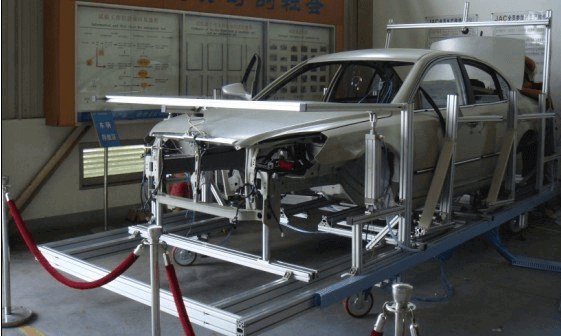
Precision machining in modern manufacturing is highly dependent on the physical interface between a machine tool and the raw stock. A CNC fixture is a special mechanical device that locates and holds the workpiece to a predetermined position relative to the cutting tool. Fixtures are attached to a particular geometry or a family of parts; they are not universal like vises or clamps.
The main definition comprises structural bases, locating elements, supporting pads and clamping mechanisms operating in absolute synchronisation. The main purpose is to restrain the workpiece in all six degrees of freedom, so that it can resist the cutting forces without elastic distortion. Key benefits include perfect dimensional repeatability, maximised spindle utilisation and dramatically reduced cycle times on batch runs. Common industries utilising advanced fixtures include aerospace, automotive, medical device manufacturing, robotics, and consumer electronics.
| Function | Description |
| Positioning | Locates workpiece accurately relative to machine coordinate system using locating pins, V-blocks, and datum surfaces. |
| Supporting | Prevents deformation and deflection under heavy cutting loads by absorbing downward and lateral forces. |
| Clamping | Holds workpiece securely against locators and supports using mechanical, hydraulic, pneumatic, or magnetic forces. |
| Repeatability | Ensures identical machining outcomes across thousands of production cycles without manual realignment. |
Why CNC Fixtures Are Important
In today’s CNC machining facilities, profitability is dictated by precision and efficiency. No matter how accurate your CNC machine is, without a well-designed fixture, it will not be able to consistently produce precision parts. Use of high-tech components allows for measurable improvements in production results:
- Improve accuracy: No human alignment error, geometric tolerances in microns.
- Increases repeatability: Ensures part-to-part location is the same over many thousands of production runs.
- Less setup time: Quick-change modular systems reduce fixture changeover downtime up to 75%.
- Higher production efficiency: Multi-part loading, automatic clamping and simultaneous multi-axis machining.
- Lower scrap rate: Avoids catastrophic crashes and dimensional drifting, thus reducing material waste to less than 0.5%.
- Improves operator safety: Contains high-pressure clamping and protects the operator from flying chips and coolant splash.
CNC Fixture vs CNC Jig
A frequent point of confusion in manufacturing terminology is the distinction between a fixture and a jig. While both are workholding devices, their fundamental functions diverge significantly regarding tool guidance.
| Feature | CNC Fixture | CNC Jig |
| Primary Function | Holds workpiece securely in place | Guides cutting tool via drill bushings |
| Machine Application | CNC milling, turning, grinding centers | Manual drilling, tapping, reaming |
| Path Determination | Machine software determines tool path | Jig bushings mechanically determine tool path |
| Rigidity | Higher rigidity for aggressive CNC feeds | Lower rigidity, focused on alignment |
When should you use a jig instead of a fixture? A jig is deployed when performing manual secondary operations—such as manual hole drilling or reaming on non-CNC drill presses—where tool guidance is critical to avoid layout errors. For automated CNC machining centers where the CNC controller dictates the toolpath, a fixture is strictly required.
Types of CNC Fixtures
Different manufacturing workflows demand specific fixture architectures. Selecting the correct type balances initial capital expenditure against production volume and part complexity.
1. Plate Fixture
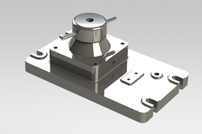
The Plate Fixture is a versatile workholding foundation with a flat metal sub-plate that is mounted directly to the CNC machine table. Custom clamps and toe clamps are used to clamp the workpiece to specific datums. The primary purpose for this is to allow complex flat or prismatic parts. The benefit is the very rigid design and the ability to customise. The downside is that the changeover times tend to be longer than modular solutions.
2. V Block Fixture
Designed especially for round parts, shafts, pins, and cylindrical components, the V Block Fixture uses 90-degree V-shaped locating surfaces. The geometry of this fixture automatically centers cylindrical stock on its longitudinal axis and prevents rotation slippage when milling or turning at high torque.
3. Modular Fixture
Built from standardized, interchangeable components (base plates, risers, clamps, V-blocks), Modular Fixtures offer unmatched flexibility for small batches, prototyping, and high-mix low-volume (HMLV) production. They eliminate the lead time of fabricating dedicated cast-iron fixtures, though their initial kit investment is high.
4. Hydraulic and Pneumatic Fixtures
Hydraulic Fixtures utilise the pressurised oil circuits to actuate heavy-duty clamping cylinders. They are indispensable in automotive and mass production environments requiring clamping forces above 10 kN. Pneumatic Fixtures, however, use compressed air, offering faster actuation times, perfect for electronics and high-speed machining of delicate parts.
5. Magnetic and Vacuum Fixtures
Magnetic Fixtures use electromagnetic or permanent magnet blocks to clamp ferrous steel plates instantly so 5-sided machining can be completed in one setup. Vacuum Fixtures hold thin aluminium, plastics, and composite panels with differential negative pressure and without mechanical distortion or marring the surface.
| Fixture Type | Best For | Cost | Accuracy |
| Plate Fixture | Prismatic, custom milled parts | Medium | Very High |
| V-Block Fixture | Shafts, cylinders, pins | Low-Medium | High |
| Modular Fixture | Prototypes, small batches | High (Initial) | Medium-High |
| Hydraulic Fixture | Automotive mass production | Very High | Extremely High |
| Vacuum Fixture | Sheet metal, thin plastics | Medium | Medium |
CNC Fixture Components
A robust CNC fixture is an assembly of specialized mechanical elements designed for precise interaction. Understanding these components is vital for proper engineering:
- Fixture base: The rigid foundation plate attaching the entire assembly to the CNC machine bed (T-slot or sub-plate).
- Locating pins: Precision-ground dowel or diamond pins establishing exact X-Y workpiece positioning.
- Support blocks: Fixed or adjustable pads beneath the workpiece absorbing downward cutting forces.
- Clamps: Mechanical, strap, or toe clamps applying downward and lateral retention force.
- Guide bush: Hardened steel bushings guiding auxiliary cutting or boring tools.
- Fasteners: High-tensile socket head cap screws and T-nuts securing fixture components.
- Stops: Fixed boundary blocks preventing linear translation during aggressive roughing passes.
- Chip clearance: Engineered pockets preventing swarf accumulation around datums.
- Coolant channel: Internal routing passages delivering high-pressure flood coolant directly to the cutting zone.
3-2-1 Locating Principle
The 3-2-1 Locating Principle represents the cornerstone of all rigorous fixture design. Every free body in three-dimensional space possesses 6 Degrees of Freedom (DoF): linear translation along the X, Y, and Z axes (3 degrees) and rotational movement around those same axes (3 degrees). To machine a part with absolute precision, all 6 degrees of freedom must be completely restrained without over-constraining.
The 3-2-1 method achieves this through three sequential planes of contact:
- Primary Plane (3 points): Placing three non-collinear support points on the primary reference datum (e.g., bottom face) restricts 3 degrees of freedom: movement along the Z-axis, rotation around the X-axis, and rotation around the Y-axis.
- Secondary Plane (2 points): Placing two locating points on an adjacent perpendicular datum (e.g., side edge) restricts 2 additional degrees of freedom: translation along the Y-axis and rotation around the Z-axis.
- Tertiary Plane (1 point): Placing a single locating point on the final perpendicular datum (e.g., end face) restricts the final degree of freedom: translation along the X-axis.
Once these 6 contact points are established, the workpiece is fully constrained, and clamping forces can be applied safely.
How to Design a CNC Fixture
Designing an industrial-grade CNC fixture requires a systematic engineering workflow to ensure safety, precision, and economic viability.
Step 1: Study Part Drawing: Analyze geometric tolerances, surface finishes, material specifications, and critical datums.
Step 2: Identify Datum: Establish primary, secondary, and tertiary datums matching the part blueprint.
Step 3: Machining Sequence Definition: The semi-finishing, roughing, and finishing operations are mapped for the prediction of the cutting force vectors.
Step 4: Select Clamping Method: Decide whether the clamping will be mechanically, hydraulically, or pneumatically activated, based on clamping force requirements and production volume.
Step 5: Design Locating System: Use 3-2-1 locating principle with hardened steel locating pins and support pads.
Step 6: Verify Tool Clearance: Perform kinematic clearance checks to ensure spindles and toolholders clear fixture walls.
Step 7: Simulation: Execute Finite Element Analysis (FEA) and collision detection simulations in CAD software.
Step 8: Manufacturing Fixture: Machine fixture plates, bases, and custom jaws to tight geometric tolerances.
Step 9: Testing: Mount the physical fixture on the CNC machine, run trial cuts, and verify part CMM inspection data.
Common Workholding Methods
Selecting the right workholding method directly influences surface finish, cycle time, and dimensional stability. Common industrial workholding methods include:
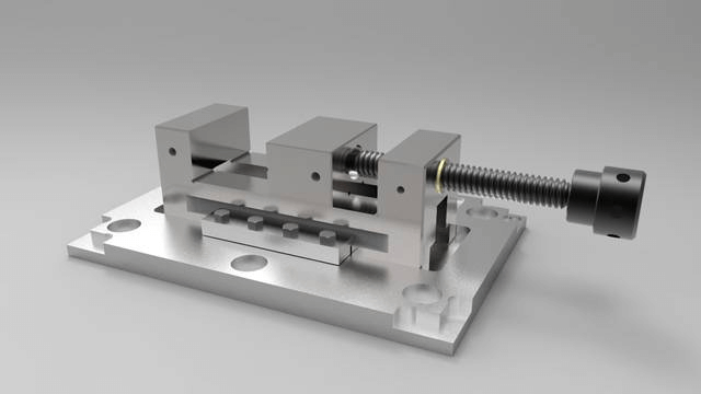
- Mechanical clamp: Manual screw clamps and strap clamps offering high rigidity and low cost.
- Hydraulic clamp: Automated high-pressure clamping for maximum holding force and rapid cycle times.
- Vacuum: Negative pressure holding for flat panels, thin plastics, and non-ferrous sheets.
- Magnetic: Electromagnetic clamping allowing unhindered 5-sided machining access.
- Pneumatic: Fast air-actuated clamping for lightweight, high-speed repetitive operations.
- Soft jaw: Custom-machined aluminum or steel jaws contoured perfectly to complex part profiles.
- Collet and Chuck: Precision rotational workholding for cylindrical bars and turned components.
Fixture Materials
The choice of material determines the life of the fixture, the damping of vibration, and the wear resistance under the harsh conditions of industrial coolant.
- Steel (Alloy Steel / 1045 / 4140): Great tensile strength and wear resistance properties. Good for high-stress clamping parts and base plates.
- Aluminium (7075-T6 / 6061-T6): Lightweight, excellent thermal conductivity and easy to machine; perfect for modular fixture plates and fast-moving pallet systems.
- Cast Iron (Grey / Ductile Iron): Gold standard in the industry, ideal for large dedicated production bases, excellent vibration damping and compressive strength.
- Engineering Plastic (Delrin / Nylon / PEEK): This plastic is non-marring, so it’s ideal for delicate cosmetic parts and aerospace parts that are sensitive to scratching.
- Tool Steel (D2 / A2): For high-contact locating pins and hardened wear plates, providing maximum surface hardness and wear resistance.
- Titanium: Utilised in niche aerospace applications demanding exceptional corrosion resistance and high strength-to-weight ratios.
Fixture Design for Different CNC Machines
The design of the fixture has to be customised to the kinematic architecture of the host CNC machine tool.
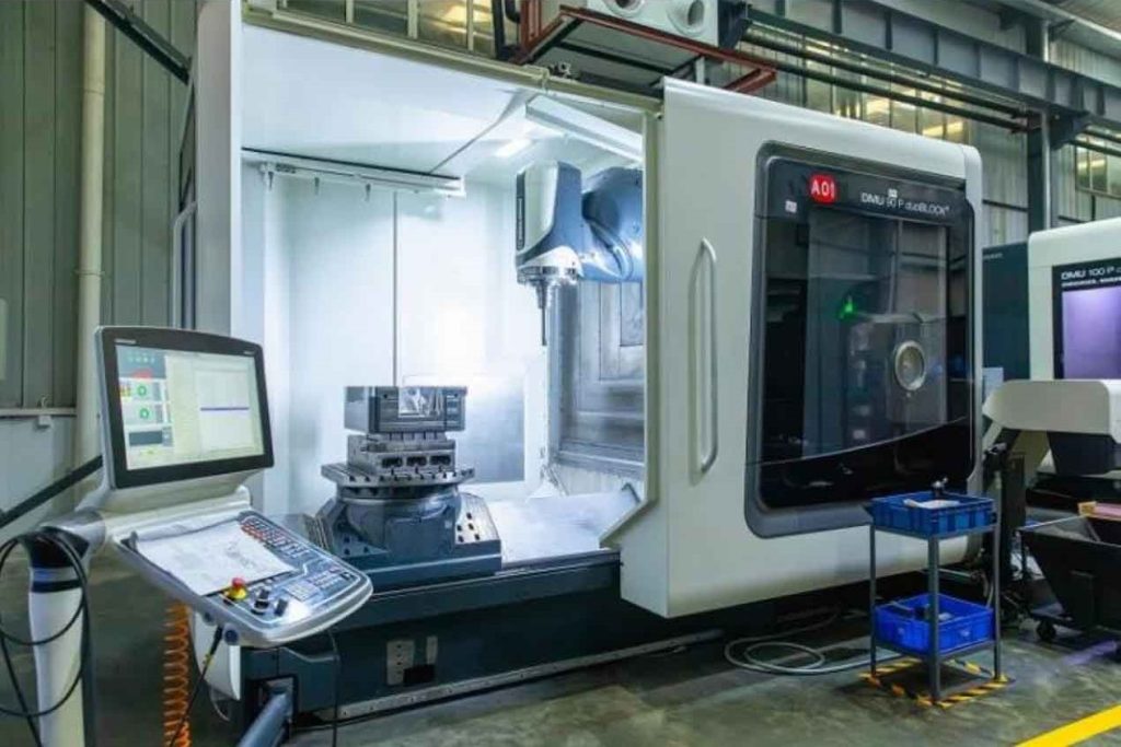
- CNC Milling Fixtures: Engineered to withstand multi-directional milling forces. Must have chip evacuation channels and strong toe clamps to prevent part lift in high feed-rate roughing.
- Fixtures for CNC turning: For rotational symmetry. Centrifugal force stress compensation, equal weight distribution, and correct chuck jaw or collet runout.
- 5 Axis Fixtures: Uses risers to lift the workpiece above the machine table. Ultra-low profile design and low clamp interference provide full 360-degree tool access on all five axes.
- Horizontal Machining Center (HMC) Fixtures: Tombstones (multi-sided vertical columns) are used to fixture multiple parts at a time, maximising spindle uptime on pallet changing systems.
- Swiss CNC Fixtures: Long, slender turned parts require the use of sliding guide bushings and sub-spindle synchronisation systems.
How to Choose the Right Fixture
Procurement and manufacturing engineers evaluate multiple variables when specifying a fixture system. The following decision matrix simplifies the selection process:
| Evaluation Factor | Primary Consideration | Recommended Solution |
| Part Shape | Prismatic vs Cylindrical vs Sheet | V-block for shafts, Plate fixture for prismatic, Vacuum for sheets |
| Production Volume | Prototype vs Mass Production | Modular fixtures for low volume; Dedicated hydraulic for mass production |
| Material Properties | Rigid steel vs Thin aluminum | Hydraulic for heavy steel; Vacuum or soft jaws for thin aluminum |
| Accuracy Requirement | Standard tolerances vs Micrometer precision | Precision ground dedicated fixtures with fixed locating pins |
| Budget Constraints | Capital expenditure limits | Modular component kits for high reusability and lower upfront tooling cost |
Common Fixture Design Mistakes
Avoiding engineering pitfalls ensures reliable, maintenance-free production runs. Here are common design flaws and their engineering resolutions:
1. Poor Locating & Over-Constraint
- Problem: Part fails to seat repeatedly on datums.
- Cause: Redundant locating points creating an over-constrained mechanical system.
- Solution: Strictly adhere to the 3-2-1 locating principle, ensuring exactly six contact constraints.
2. Weak Clamping & Part Distortion
- Problem: Workpiece springs out of tolerance after unclamping.
- Cause: Excessive clamping force applied directly over unsupported thin walls.
- Solution: Introduce backup support blocks directly beneath clamping points and optimize hydraulic clamping pressure.
3. Insufficient Chip Evacuation & Coolant Flow
- Problem: Chips pack around locating pins, causing dimensional drift.
- Cause: Lack of swarf clearance pockets and coolant channels.
- Solution: Design 45-degree chip drainage chutes and integrate high-pressure through-fixture coolant flushing.
4. Tool Interference & Collision
- Problem: Spindle or toolholder strikes fixture clamps during multi-axis profiling.
- Cause: Inadequate kinematic clearance verification in CAD.
- Solution: Perform full digital simulation and utilize low-profile pneumatic swing clamps.
Industry Applications
Specialized fixtures drive productivity across diverse high-tech manufacturing sectors:
- Automotive: Typical parts include engine blocks and transmission housings. Fixture requirement: Heavy-duty hydraulic multi-part clamping. Recommended solution: Cast-iron dedicated hydraulic tombstone fixtures.
- Medical: Typical parts include titanium bone plates and spinal implants. Fixture requirement: High biocompatibility and extreme precision. Recommended solution: Stainless steel modular or custom soft-jaw vises.
- Aerospace: Typical parts include turbine blades and structural airframe bulkheads. Fixture requirement: Complex contoured support and vibration damping. Recommended solution: Vacuum-assisted conformal epoxy resin or custom cast aluminum fixtures.
- Robotics & Industrial Equipment: Typical parts include gearbox housings and mounting brackets. Fixture requirement: High rigidity and fast load/unload cycles. Recommended solution: Pneumatic quick-change sub-plate systems.
- Semiconductor & Electronics: Typical parts include aluminum chassis and vacuum manifolds. Fixture requirement: Zero surface scratching and tight flatness control. Recommended solution: Vacuum chucks and Delrin-lined modular fixtures.
Frequently Asked Questions
What is the difference between a CNC fixture and a jig?
A CNC fixture holds and positions a workpiece securely while the CNC machine program dictates the cutting toolpath. A jig not only holds the workpiece but also incorporates hardened steel bushings to mechanically guide cutting tools (such as drills or reamers), predominantly used in manual operations.
What is the 3-2-1 locating principle?
It is a fundamental workholding rule used to constrain all 6 degrees of freedom of a workpiece in 3D space. It uses 3 points on a primary plane, 2 points on a secondary plane, and 1 point on a tertiary plane to achieve absolute positioning repeatability.
What materials are commonly used for CNC fixtures?
Common materials include alloy steel (4140/1045) for high-strength components, aluminum (7075/6061) for lightweight modular plates, cast iron for superior vibration damping in dedicated bases, and tool steel (D2) for wear-resistant locating pins.
How do fixtures improve machining accuracy?
Fixtures eliminate human alignment errors, absorb heavy cutting vibrations, prevent workpiece deflection under clamping pressure, and ensure identical part positioning across thousands of production cycles.
What is the best fixture for 5-axis machining?
Low-profile modular vises, dovetail clamping fixtures, and zero-point clamping risers are ideal because they elevate the workpiece and eliminate clamp clashing, allowing unobstructed 360-degree tool access.
How often should CNC fixtures be calibrated?
Fixtures should undergo routine visual inspection daily, cleaning after every batch, and dimensional re-calibration via CMM or laser tracking every 3 to 6 months depending on production volume and wear.