
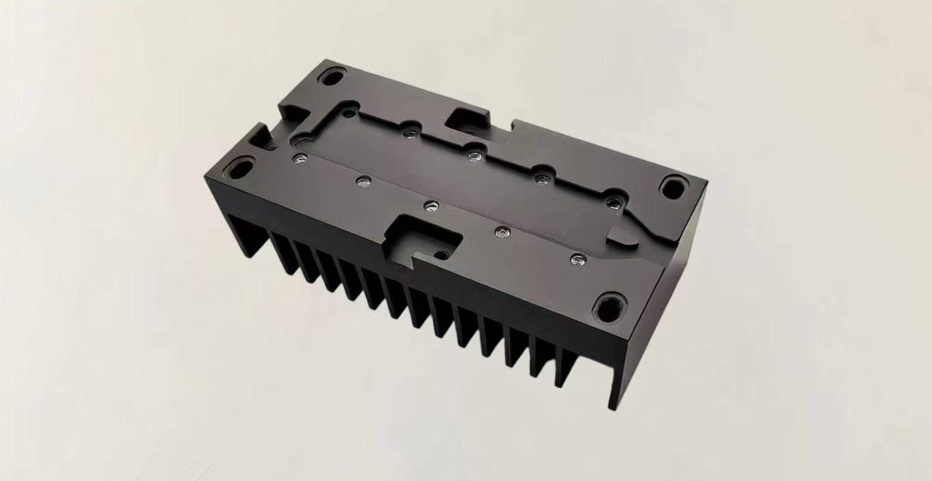
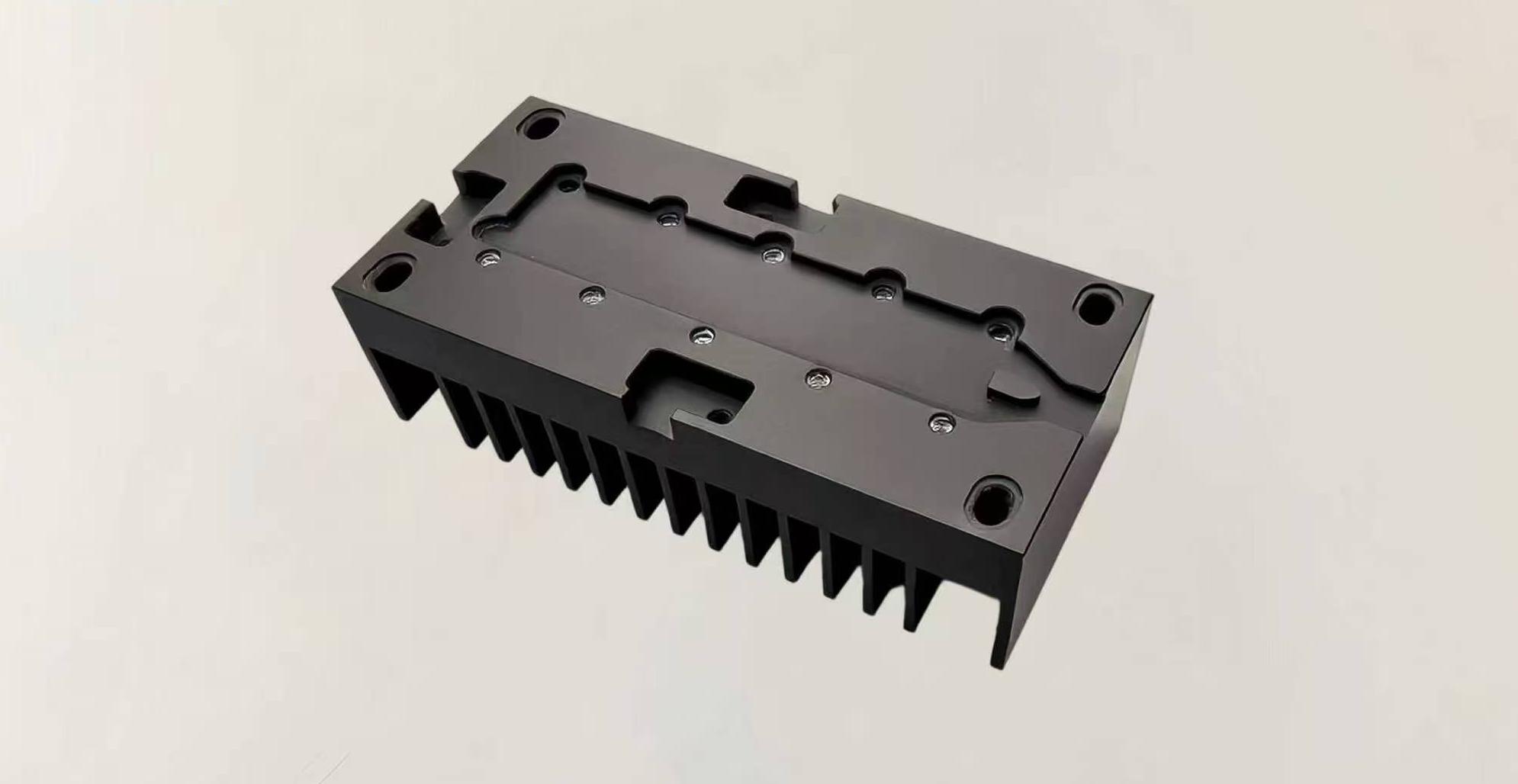
CNC Machined Mounting Base with Cooling Fins
- Material: AL 5083
- Size: 42X91X25 mm
- Process: CNC Machining
- Surface treatment: Black Anodizing
Machining Approach
The part is cut from an aluminum block. We first rough mill the top mounting face, the outer profile, and the relief pockets. The part is then flipped on a locating fixture to mill the dense cooling fins on the underside. Next come the finish machining of the counterbored holes and locating steps. Every area is deburred and cleaned, and the part is finished with black anodizing.

The Tricky Parts of This Part
- The cooling fins are thin and long. They readily pick up chatter marks while being cut, and they can also spring away from the tool and distort.
- The gaps between fins are very narrow. Aluminum chips get trapped in there and are hard to clear.
- The top face needs high flatness. It decides how well the part sits against the heat source, which is to say how well heat is transferred.
- Both sides need to be clamped. The datum can easily shift when the part is flipped.
- Anodizing slightly changes the counterbored holes. Both the depth and the diameter can change by a small amount.
How We Get It Right
| Problem | Approach |
| Fin chatter and distortion | Aluminum-specific tools, high spindle speed, shallow depth of cut, and layered climb milling of the fins |
| Chips that will not clear | Compressed air blast used throughout the cut to keep blowing the chips out |
| Datum shift when flipping | The datum is established on the first side, and a pin-locked fixture is used when flipping to reduce clamping error |
| Top face flatness | The mounting face is finish milled last, which gives better control of flatness |
| Counterbore change after anodizing | An anodizing allowance is left when machining the counterbores, and the holes are cleaned out again after anodizing if needed |