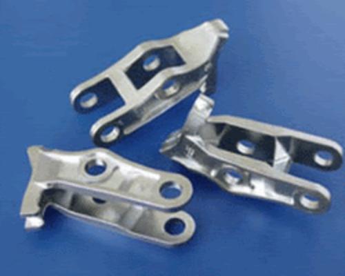
In modern manufacturing, the accuracy of a mold directly affects the dimensional accuracy and surface quality of the final mass-produced part. The traditional tool and die making was very much dependent on hand skills, which limited the throughput and introduced human error. Computer Numerical Control (CNC) technology solves these production bottlenecks by automating toolpaths and optimizing material removal. With today’s CNC mold manufacturing, production facilities can routinely hold tolerances as tight as±0.005 mm on complex cavities, dramatically reducing cycle times and eliminating handwork on the bench.
CNC Techniques for Mold Design
The manufacturing phase of a mold is entirely dependent on the digital architecture established during the design stage. Modern CNC mold making integrates computational analysis to eliminate geometry errors prior to physical cutting.
1. CAD/CAM Software Integration
Computer-Aided Design (CAD) and Computer-Aided Manufacturing (CAM) serve as the foundation of digital tooling. Designers utilize CAD software (such as UG NX, SolidWorks, and Autodesk Inventor) to generate exact 3D solid models of the cavity, core, sliders, and ejector systems.
After that gets finalized, the same data moves into CAM software (like Mastercam or Powermill). Then the CAM system figures out specialized toolpaths, and it outputs the exact G-code and M-code commands that essentially control the machine, including spindle speed, feed rates, plus the multi-axis positioning.
2. Simulation and Analysis Before Machining
Designers run algorithmic simulations to reduce the financial risk of breakage of scrap material or tools:
- Moldflow Analysis: Simulates the behaviour of thermoplastic in the cavity to find potential air traps, weld lines and optimum gate locations.
- Finite Element Analysis (FEA): assess the stress in the structure and heat distribution, to ensure that the mold base can resist mechanical deformation when the clamping pressure is higher than 1000 tons.
- Kinematic Collision Detection: Guarantees that the computed toolpath allows the cutting tool and holder to clear all fixtures without colliding with the raw workpiece.
3. 3D Scanning for Reverse Engineering
If digital blueprints are not available, e.g., for legacy tooling components or physical prototypes, then high-resolution 3D laser scanning is used to capture spatial coordinates. This point cloud data is then reconstructed into an editable parametric model in CAD software that allows for identical replication or engineering optimization of the mold.
4. Parametric, Feature-Based Design & Knowledge-Based Engineering (KBE)
Parametric modeling relates geometric features to mathematical relations. For example, when the shrinkage rate of a certain polymer is changed, the entire cavity assembly is scaled automatically. KBE: Knowledge-Based Engineering. This is where you embed the design rules into the software, for example: Draft angle requirements, cooling channel clearance limits, etc. This automates the ” trivial ” decisions and puts hard limits on the manufacturing standards.

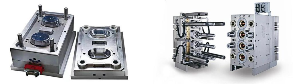
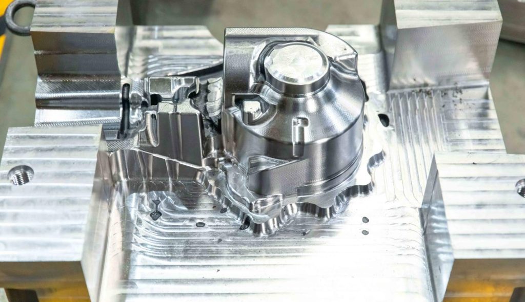
Primary CNC Machining Techniques
Subtractive manufacturing in toolmaking requires specific machinery configurations depending on the geometry, hardness, and required surface finish of the component.
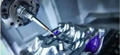
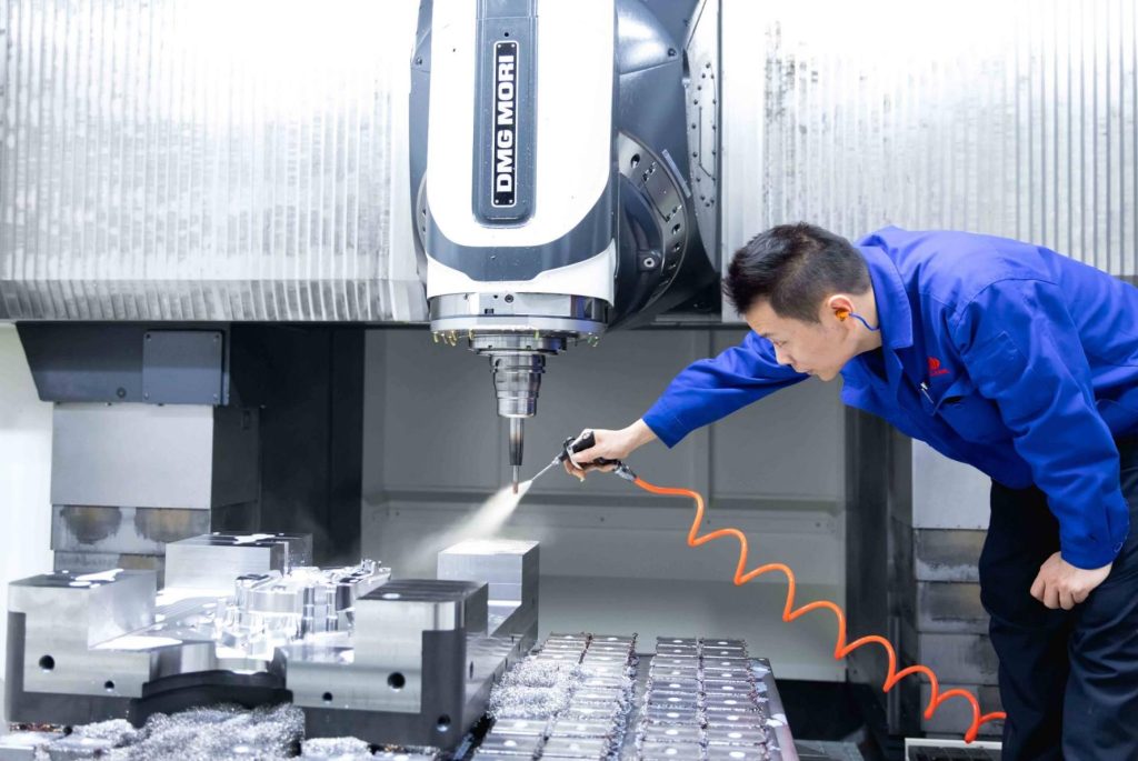
1. CNC Milling
CNC Milling is still the preferred method for bulk material removal and complex profiling. The machine systematically strips stock from a stationary block of tool steel using rotating cutting tools. 3-axis milling moves in the traditional X, Y and Z coordinate planes and works well for flat parting lines and open cavities. But when you have complex contours, you need more sophisticated toolpaths to keep the chip load consistent.
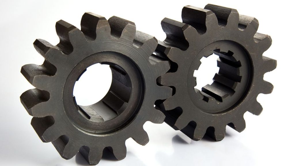
2. CNC Turning
For parts with radial symmetry, such as core pins, guide bushings or round mold cavities, CNC Turning is used. The workpiece is rotated at high speed and a rigid, single-point cutting tool machines the outside or inside diameters. Live tooling is now available on modern turning centers and allows secondary milling and cross-drilling to be performed on the same machine without moving the workpiece.
3. Electrical Discharge Machining (EDM)
Electrical Discharge Machining is necessary for deep, narrow slots and sharp internal corners, which cannot be reached by cutting tools. EDM processes do not exert any mechanical force and so can be used to machine hardened steels without inducing stress.
- Sinker EDM: Utilizes a specially shaped electrode of copper or graphite, immersed in dielectric fluid. High-frequency electro-sparks erode the mirror image of the electrode into the workpiece.
- Wire EDM: Employs a continuously fed electrically charged brass wire (generally 0.20 mm to 0.25 mm diameter) to cut very accurate, vertical or tapered profiles through thick steel plates.
4. CNC Grinding
Components are CNC ground for a hermetic seal along the mold parting line and to prevent plastic leakage (flash). Automated surface and cylindrical grinding machines are equipped with vitrified abrasive wheels, which provide high flatness and mirror-like finishes, resulting in surface roughness values as low as Ra 0.1 μm.
Subtractive Process Selection for Mold Making
The following matrix outlines the operational capabilities and technical constraints of each primary subtractive process used during mold production.
| Technique | Best For | Tolerance / Surface Finish | Limitations |
| 3-Axis & 5-Axis Milling | Deep 3D cavities, core blocks, rapid roughing | ±0.010 mm / Ra 0.8 μm | Restricted by tool diameter; cannot cut sharp internal 90° corners |
| Sinker EDM | Blind cavities, sharp internal corners, rib grooves | ±0.005 mm / Ra 0.4 μm | Slow material removal rate; requires separate electrode fabrication |
| Wire EDM | Through-holes, extrusion dies, core inserts | ±0.002 mm / Ra 0.2 μm | Limited to conductive materials and straight through-cut geometries |
| CNC Grinding | Parting lines, slider guides, interlocking blocks | ±0.001 mm / Ra 0.1 μm | Limited to simple geometric profiles and flat or cylindrical surfaces |
Advanced and Future Techniques
As component geometries become more intricate, conventional machining methods reach their physical limits, necessitating advanced technological alternatives.
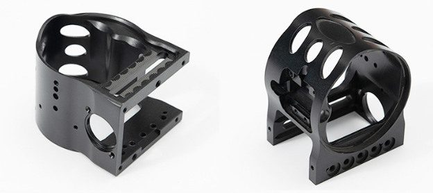
1.5 Axis Machining
A 5-axis CNC machine is different from a traditional machining center in that it moves the tool or workpiece along 5 different axes at the same time (X, Y, Z, A and B). The present setup allows for cutting tools to be exactly perpendicular to complex curved surfaces.
This avoids multiple setups and minimizes cumulative positioning errors. It also allows the use of shorter, stiffer end mills, which results in less tool deflection and improved final surface finish.
2. High Speed Machining (HSM)
High-Speed Machining utilizes spindle speeds exceeding 15,000 RPM coupled with low radial cut depths. The rapid feed rates ensure that the heat generated during deformation transfers directly into the flying chips rather than radiating into the mold core. This eliminates thermal distortion, allowing production facilities to safely machine pre-hardened steels up to 60 HRC.
3. Micromachining and Hybrid Machining
Micromachining is the fabrication of molds for microfluidic chips, medical connectors and micro-optics, using microscopic cutting tools and high-magnification vision systems.
At the same time, Hybrid Machining is the integration of additive and subtractive processes in one workstation. The tool core with internal, curved conformal cooling channels that follow the contours of the cavity is printed by laser powder bed fusion. The integrated CNC mill finishes the printed surface to precise dimensional specifications immediately.
FAQs
1. When would a manufacturer choose to use CNC milling over EDM for mold cavities?
CNC milling is chosen for bulk material removal and large, accessible geometries because it processes much faster. EDM is used for parts with deep channels, zero-radius internal corners or when the workpiece material has been heat-treated to maximum hardness, so that mechanical cutting tools become ineffective.
2. What are the measurable benefits of 5-axis CNC machining in toolmaking?
It allows a reduction of up to 75% of total production setups. The angular articulation allows shorter cutting tools to reach deep cavities, reducing chatter, extending tool life and providing better surface finishes, which cuts manual polishing time by over 50%.
3. What are the basic raw materials used in CNC mold making and why?
- Aluminum 7075-T6: Used for low-volume production runs and prototyping because it has very high thermal conductivity and machines rapidly.
- P20 / NAK80 Steel: Pre-heat-treated tool steels for medium production injection molds. Good dimensional stability, and does not require heat treatment after machining.
- H13 / S136 Steel: High alloy chromium steels used for high volume injection molds and die casting dies. They have a very high wear resistance and are able to withstand millions of production cycles after hardening processes.