

CNC programming forms the basic communication process behind today’s precise manufacturing. The heart of the whole thing is the two instruction languages, G-Code and M-Code. They stand for machine coordinates and auxiliary automation hardware. In an era where complex Computer-Aided Manufacturing (CAM) software pipelines are the standard, a solid capability to directly read code is still a critical skill for engineering verification, safe setup, optimization routines, and rapid on-machine troubleshooting. This comprehensive reference describes their various syntax, operational architectures and implementation paradigms, proven in the field.
What Is CNC Programming?
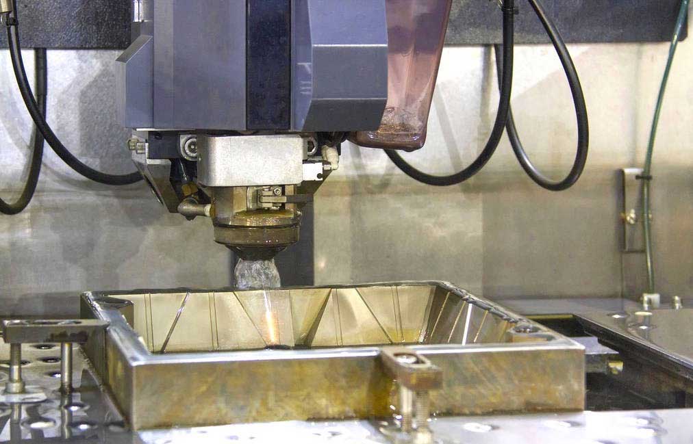
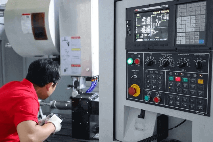
CNC (Computer Numerical Control) programming is the process of generating a sequential set of precise alphanumeric instructions that command automated machine tools—such as mills, lathes, routers, and EDM machines—to shape raw stock materials into exact physical components. The structural integrity and precision of the finished component depend entirely on the semantic accuracy of these programmed instructions.
How CNC Machines Interpret Programs
Modern manufacturing utilizes a highly integrated digital-to-physical thread. The transition from a conceptual design to physical toolpaths follows a strict, sequential pipeline:
| CAD 3D Model Design | → | CAM Toolpath Generation | → | Post Processor Machine Translation | → | G/M Code Raw CNC Syntax | → | Controller MCU Interpretation | → | Machine Motion Physical Execution |
The engineering workflow initiates within Computer-Aided Design (CAD) software, defining the exact geometric boundaries. The resulting model is imported into Computer-Aided Manufacturing (CAM) software, where specific machining parameters—tool selections, stepovers, stepdowns, and feed rates—are configured. Crucially, CAM software outputs an idealized generic vector path. This path passes through a machine-specific Post Processor, translating software paths into exact G-Code and M-Code parameters tailored precisely to the kinematics, controller model, and physical constraints of the targeted CNC machinery
Why G-Code and M-Code Are the Foundation of CNC Machining
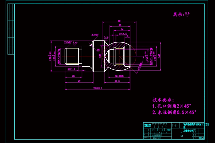
Regardless of how sophisticated a CAM system becomes, a CNC machine controller (such as Fanuc, Siemens, Haas, or Mazak) cannot execute native CAD/CAM files directly. Every operation is resolved into raw electrical signals controlling physical axes. These resolved tasks are categorized into two fundamental modes:
- Motion Commands (G-Code): Dictate the spatial coordinates, paths, interpolation velocities, and foundational frame of reference for the cutting tool.
- Machine Operational Commands (M-Code): Actuate peripheral hardware systems such as spindle relays, fluid pumps, pallet changers, and structural safety enclosures.
What Is G-Code?
G-Code, or Preparatory Code, comprises the instructions that dictate the geometric path, coordinate alignment, velocity, and direct physical movement profiles of the machine tool relative to the raw workpiece material.
What Does G-Code Control?
G-Code governs all aspects of geometric spatial translation, material removal pathways, and coordinate system shifts. Its core control functions include:
- Tool Movement & Positioning: Moving cutting tools between processing locations rapidly or along controlled cutting paths.
- Interpolation Schemes: Defining whether tools move in linear vectors, precise circular arcs, or complex non-linear splines.
- Coordinate Systems: Shifting reference datums from machine home configurations to localized part setup zeros (e.g., G54 through G59 systems).
- Feed Motion Units: Setting the structural movement basis, configuring inputs as feed per minute or feed per revolution.
How G-Code Works
G-Code statements are formatted into structured alphanumeric terms that controllers parse line by line. Consider the following industry-standard syntax example:
| G00 X10.5 Y25.0 |
When this block is parsed by the Machine Control Unit (MCU), it is broken into discrete instructions:
- G00 (Command Type): Calls the rapid traverse mode. It forces all axes involved to run their maximum traverse acceleration profiles and immediately move to target positions.
- X10.5 (Target X Coordinate): Instructs the physical X-axis ball screw/servo loop to move to the linear coordinate value of 10.5 exactly.
- Y25.0 (Target Y Coordinate): Instructs the Y axis control loop to move in parallel to the linear coordinate value of 25.0.
Modal vs. Non-Modal G Codes
The persistence behavior of commands is essential to write clean programs and avoid physical tool collision:
Modal Codes: These codes are activated and stay in the controller’s memory until they are cancelled or overridden by another code in the same functional group. For example, when G01 (Linear Interpolation) is declared, all the subsequent lines with coordinate values will be interpreted as linear cuts until it’s canceled by G00, G02, or G03.
Non-Modal Codes: Affect only the block (line) where they are written. One good example is the dwell command G04. It pauses the axes’ motion for a given time only on that line; the next lines resume immediately using the default motion parameters.
What Is M-Code?
M-Code or Miscellaneous Code (often called Auxiliary Code) governs the basic electromechanical capabilities and structural functions of the machine tool itself rather than spatial axis trajectories.
What Machine Functions Does M-Code Control?
The M-Codes are directly connected to switches, valves, and relays controlled by the machine’s Programmable Logic Controller (PLC). The M-codes control key structural systems, including:
- Spindle Activation & Rotation: Instructions to rotate the spindle clockwise (M03), counter-clockwise (M04), or stop the spindle immediately (M05).
- Coolant Management: Enable flood coolant pumps (M08), high-pressure through spindle coolant loops, or completely disable fluid systems (M09).
- Automation & Ancillary Systems: Automated tool changes (M06), tool carousel indexing, automatic door actuation, parts catchers or robotic loading cycles.
- Program Execution Control: Optionally stop program loops (M01) or define states to completely terminate and reset the routine (M30).
Why M-Codes Are Machine-Specific
While standard G-codes governing basic movements are broadly standardized by international bodies (ISO/EIA), M-codes depend closely on the unique mechanical design and PLC integration chosen by the machine tool builder (OEM). A command that executes an automatic pallet change on a Haas horizontal machining center may trigger a completely different auxiliary relay or be invalid on a Fanuc-controlled multi-tasking lathe. Machinists must always consult the original equipment manufacturer’s manual to confirm specific M-code functions before executing code on unfamiliar hardware.
G-Code vs. M-Code: What’s the Difference?
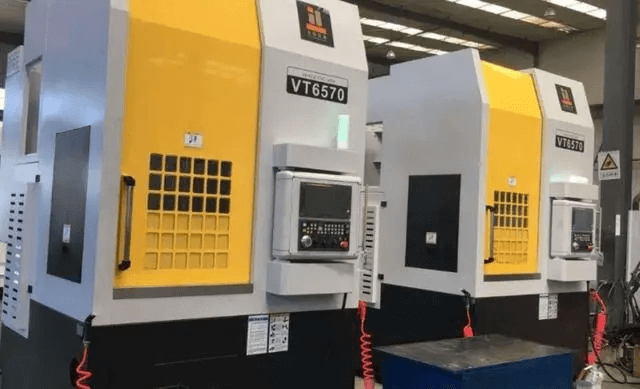
When programming a CNC machine, G-code determines where the tool moves, while M-code determines what the machine does.
| Feature | G-Code (Preparatory) | M-Code (Miscellaneous) |
| Primary Purpose | Manages geometric toolpaths, motion vectors, and positioning profiles. | Manages auxiliary machine functions and hardware states. |
| Controlled Systems | Servo motors, linear ball screws, rotary axes, and coordinate offsets. | Spindle relays, coolant pumps, automated doors, and tool changers. |
| Standard Syntax Examples | G00, G01, G02, G03, G54, G90 | M03, M05, M06, M08, M09, M30 |
| Coordinate Values | Requires direct axis parameters (e.g., X, Y, Z, R, I, J). | Standalone execution or limited secondary parameters. |
| Standardization Level | Highly uniform across standard control platforms (ISO/EIA). | Varies significantly based on specific machine builders. |
How G-Code and M-Code Work Together
In a standard production environment, G-codes and M-codes operate as a tightly synchronized script. Geometric motion cannot proceed safely without first setting up the correct physical environment via auxiliary commands.
Operational Execution Workflow Pipeline:
▪ Tool Change (M06)
▪ Spindle Start Clockwise (M03)
▪ Rapid Position Above Part (G00)
▪ Activate Flood Coolant (M08)
▪ Linear Controlled Cutting (G01)
▪ Circular Contour Milling (G02/G03)
▪ Deactivate Coolant Pump (M09)
▪ Spindle Rotation Stop (M05)
▪ Program End and Rewind (M30)
This structural flow highlights how G-codes and M-codes complement each other. The tool changer (M06) prepares the correct geometry, the spindle starts (M03), and the axes move rapidly into place (G00). Once coolant flows (M08), the controlled cutting path (G01) begins. Finally, tool path execution and auxiliary shutdown proceed sequentially to reset the machine for the next cycle.
Most Common G Codes Every CNC Programmer Should Know
| Code | Meaning | Typical Application | Syntax Example |
| G00 | Rapid Positioning | Non-cutting, fast repositioning movements. | G00 X50.0 Y100.0 Z10.0 |
| G01 | Linear Interpolation | Straight-line controlled material cutting. | G01 Z-5.0 F150 |
| G02 | Circular Interpolation (CW) | Milling precise clockwise arcs or full circles. | G02 X20.0 Y20.0 R10.0 F200 |
| G03 | Circular Interpolation (CCW) | Milling precise counter-clockwise arcs. | G03 X10.0 Y30.0 R15.0 F200 |
| G04 | Dwell | Pausing axis movement to clear chips or finish corners. | G04 P1000 (1-second pause) |
| G17 / G18 / G19 | Plane Selection | Selecting active planes (XY, ZX, YZ) for arc interpolation. | G17 (Selects XY Milling Plane) |
| G20 / G21 | Unit Selection | Setting system units to inches (G20) or millimeters (G21). | G21 (Enforces metric mode) |
| G28 | Return to Home Position | Sending axes back to physical machine zero reference. | G28 G91 Z0 |
| G40 / G41 / G42 | Cutter Compensation | Offsetting tool paths left/right to account for tool radius. | G41 D01 X10.0 Y10.0 |
| G43 | Tool Length Compensation | Applying tool length offset values from registry. | G43 H01 Z5.0 |
| G54 – G59 | Work Coordinate Systems | Selecting active localized workpiece datum setups. | G54 (Primary work offset) |
| G90 | Absolute Positioning | Interpreting all coordinates from the fixed datum zero. | G90 G01 X50.0 |
| G91 | Incremental Positioning | Interpreting movements relative to the tool’s current position. | G91 G01 X10.0 |
Most Common M Codes Every CNC Programmer Should Know
| Code | Purpose | Application | Typical Example |
| M00 | Program Stop | Unconditional pause for manual inspection or part flipping. | M00 (Halts machine absolute) |
| M01 | Optional Stop | Pauses execution only if the physical switch on the control panel is active. | M01 (Selective operator check) |
| M03 | Spindle On (Clockwise) | Starts main spindle rotation in standard cutting direction. | S2500 M03 |
| M04 | Spindle On (Counter-Clockwise) | Starts spindle rotation in reverse direction (e.g., left-hand tapping). | S1200 M04 |
| M05 | Spindle Stop | Cuts electrical power to the spindle motor, bringing it to rest. | M05 (Spindle spin down) |
| M06 | Automatic Tool Change | Swaps the active spindle tool with a specified tool number. | T02 M06 (Loads Tool #2) |
| M08 | Coolant On (Flood) | Actuates the primary coolant pump valve. | M08 (Initiates fluid delivery) |
| M09 | Coolant Off | Closes all active coolant delivery circuits. | M09 (Terminates fluid delivery) |
| M30 | Program End and Reset | Stops execution, turns off indicators, and rewinds to the first block. | M30 (Concludes active cycle) |
Sample CNC Program Explained Line by Line
To demonstrate how these concepts combine into a unified manufacturing sequence, look at this verified, standard block of code designed to profile a simple pocket outline:
| % O1001 G21 G90 G54 T01 M06 S3000 M03 G00 X0 Y0 G43 H01 Z50.0 M08 G01 Z-2.0 F200.0 G01 X100.0 F400.0 G02 X150.0 Y50.0 R50.0 M09 M05 G28 G91 Z0 M30 % |
Below is the granular engineering interpretation of each command line within the program structure:
| Line Block | Syntactical Meaning | Physical Machine Real-Time Action |
| % | Program Flag Delimiter | Signals the controller memory input buffer that data transmission is starting. |
| O1001 | Program Identification Number | Registers this specific routine as program number 1001 within the storage matrix. |
| G21 G90 G54 | Safety Initialization Block | Sets system units to millimeters (G21), enables absolute positioning (G90), and activates the first work coordinate fixture datum (G54). |
| T01 M06 | Tool Call & Change Command | Indexes the physical tool carousel to pocket #1 and executes an automatic tool swap into the main spindle. |
| S3000 M03 | Spindle Velocity & Direction Call | Sets spindle rotation velocity to 3000 RPM and engages clockwise rotation. |
| G00 X0 Y0 | Rapid X/Y Axis Alignment | Drives the X and Y axes simultaneously at rapid traversal velocity to the localized part zero datum point. |
| G43 H01 Z50.0 | Tool Length Offset Call | Reads length tracking register #1, applies height compensation, and positions the tool safely at 50.0mm above the material surface. |
| M08 | Fluid Pump Engagement | Opens the primary delivery valve, streaming flood coolant directly onto the machining zone. |
| G01 Z-2.0 F200.0 | Controlled Z Axis Entry | Plunges vertically down into the raw material to a depth of Z = -2.0mm at a controlled cutting feed rate of 200mm/min. |
| G01 X100.0 F400.0 | Linear Milling Cut | Machines a straight profile cut along the X-axis to coordinate value X = 100.0mm, increasing feed velocity to 400mm/min. |
| G02 X150.0 Y50.0 R50.0 | Clockwise Arc Milling Pass | Interpolates a smooth clockwise circular arc ending exactly at X=150.0, Y=50.0 with a precise arc radius profile of 50.0mm. |
| M09 | Fluid Pump Disengagement | Shuts off flood coolant flow prior to moving the tool out of the cutting zone. |
| M05 | Spindle Deceleration | Brings the spindle motor rotation to a controlled stop. |
| G28 G91 Z0 | Z Axis Retraction to Home | Retracts the Z-axis vertically in incremental mode directly to the physical machine home position to clear tool changers. |
| M30 | Routine Termination | Concludes active program execution, drops system states, and returns the cursor to the top of file line O1001. |
| % | Program Terminal Flag | Signals the data transmission buffer that data input is complete. |
Common CNC Programming Mistakes Beginners Should Avoid
Programming errors can lead to costly shop issues like ruined workpieces, broken cutting tools, or deadly spindle crashes. Here’s a list of common implementation errors and how to fix them:
- Wrong Coordinate System Choice: Creating coordinate moves without G90 (Absolute) or G91 (Incremental). If a controller expects absolute points but reads incremental inputs, the tool path will move dangerously out of limits.
- Forgetting Tool Length Offsets (G43 / H_): Calling for a Z-axis depth adjustment without calling the tool length offset register (G43 Hxx). Without this correction, the controller can not find the position of the tip of the tool, which often causes a heavy collision in the Z axis with the part or table.
- Missing Spindle Activation Commands: Specifying a linear cutting path (G01) but not providing a spindle velocity value (S) and direction command (M03/M04). A tool that is fixed will fail immediately when pushed into raw stock material.
- Forgetting Coolant Commands When Machining Tough Materials: Not activating flood coolant (M08) when machining tough materials such as titanium or stainless steel. This results in rapid heat buildup, which ruins tool edges and causes material work-hardening.
- Unsafe Rapid Positioning Clearances: Rapidly repositioning tools (G00) too close to clamping fixtures, raw stock profiles, or raw component corners. Always establish a clear, high clearance floor above all obstacles.
Best Practices for Writing Safe and Efficient CNC Programs
Veteran programmers use a disciplined structure to minimize risk and to maximize throughput on the floor of the factory;
- Always Run Full Virtual Simulations: Don’t load a newly post-processed file straight to production without first checking the toolpaths inside a graphical verification simulator or running a dry run above the part setup.
- Explicitly Check Active Work Offsets: Make sure each individual setup block explicitly begins with a defined work coordinate call (G54, G55, etc.) so the controller doesn’t reference the wrong machine datums.
- Use Clear Explanatory Comments: Enclose legible notes in parentheses, e.g. (T1 – 12mm ENDMILL) or (ROUGH OUTER PROFILE) to help machine operators properly set up and follow operations.
- Keep Modal Blocks Formatted and Clear: Keep the active structural codes together in the first few lines of the program (the “safety block”) so the machine state is clean and predictable at each start.
- Confirm Tool Length Offset Matching: Ensure that the H-register ID number matches the active physical tool slot number (e.g., T01 must always run with H01).
G-Code and M-Code in Modern CAM Software
Modern manufacturing is shifting toward automated workflows using suites such as Autodesk Fusion 360, Mastercam, Siemens NX, and PowerMill. CAM software automatically generates long and complex G-code scripts. But blind faith in the output from automated software is a huge operational risk. There are still many reasons why it’s a valuable skill to know how to read and edit raw code:
- Real-Time Program Debugging: When a machine experiences a generic motion error or strikes a software limit switch during a cycle, a skilled programmer can read the current code block on the controller screen to promptly pinpoint and rectify the error without returning to the engineering office.
- Dynamic Feed and Speed Tweaking: In mass production environments, programmers often tweak feed codes (F) and spindle values (S) directly on the shop floor to optimize cycle times and improve surface finishes in real time.
- Post-Processor Customization: Generic CAM post-processors tend to produce generic code blocks with unnecessary tool motions or do not support special auxiliary options on machines. If you know how the raw code works, you can tweak the post-processor so it generates cleaner and more efficient scripts.
Frequently Asked Questions (FAQs)
Can G-code and M-code appear on the exact same line block?
Yes, standard CNC controllers allow programmers to put G-codes and M-codes on the same line if they do not cause conflicting instructions. For instance, writing G00 X50.0 Y100.0 M08 is perfectly valid; the machine moves rapidly to the target coordinates while simultaneously opening the flood coolant valve.
What happens if I write a code that my machine controller does not support?
If the controller reads an unsupported command, it will throw an execution alarm (such as “Improper G-Code” or “Unrecognized Command”) and immediately halt all axis motion and spindle rotation. This safety mechanism prevents unpredictable machine behavior.
Why do different machines use different G-codes for the exact same function?
While basic movements like linear interpolation (G01) are standard across the industry, specialized functions—such as canned drilling cycles or custom macro options—depend on how the machine controller software was designed. For example, a Fanuc controller and a Mazak controller may use slightly different codes to handle complex canned boring cycles.