

In turning, chip control is the make-or-break factor for machining efficiency, tool life, and the continuity of automated production. With lights-out manufacturing and unattended machining becoming the new normal, chip breaking has gone from a “nice-to-have” to an absolute must. One hour of downtime on a CNC lathe because of tangled chips doesn’t just cost you production – it costs you customer trust.
So how do you actually solve CNC turning chip breaking? This article walks through the fundamentals and several battle-tested methods from JTR Machine’s experience with stainless steel, titanium, and aluminum alloys – written for process engineers and procurement decision-makers who need practical answers, not fluff.
Why Chip Breaking Actually Matters
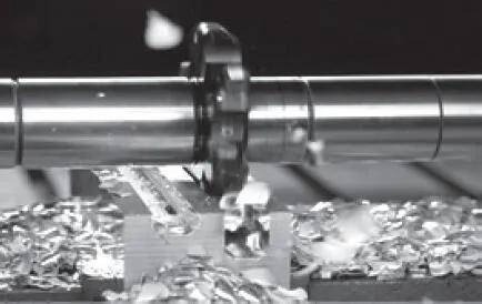
Automated equipment has zero tolerance for messy chips. Once chips wrap around the tool, tangle on the workpiece, or jam the chip conveyor, you’re looking at surface defects at best – and equipment damage or safety incidents at worst.
Bottom line: chip breaking isn’t about making things look tidy – it’s about keeping the machine running. In batch production, one chip-related stoppage can cost you 15–30 minutes of cleanup and restart time. On an unattended night shift? That could wipe out an entire night’s output.
Whether chips break easily comes down to one thing: the amount of deformation the chip undergoes during cutting. As metal goes through severe plastic deformation, its hardness increases while plasticity and toughness drop significantly – that’s work hardening in action. Once the chip gets hard and brittle, it snaps when bent or impacted. More deformation = more hardening = easier chip breaking.
So the core strategy is simple: make the chip more brittle – either by designing the tool geometry to increase deformation, or by using cutting parameters or programming techniques to create impact forces.
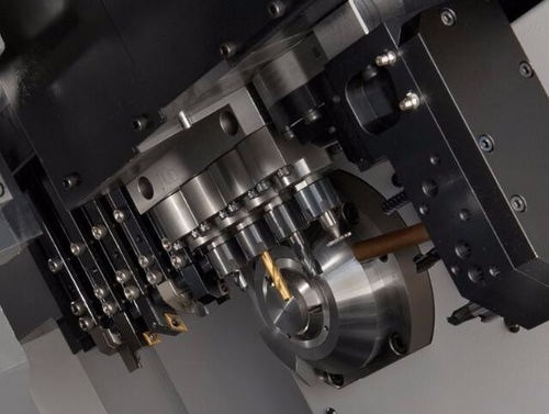
Common Chip Breaking Methods – A Deep Dive
Method 1: Tool Geometry Solutions (Material Deformation Approach)
This is the most widely used and most mature chip breaking strategy. The idea is simple: design the tool so the chip gets “worked over” enough during formation that it breaks on its own.
1. Chipbreakers – The Go-To Solution
Chipbreakers are the most common chip breaking method out there. By pressing specific groove shapes into the rake face of carbide inserts, they force the chip to curl and bend as it flows out, eventually snapping.
Indexable carbide inserts come with all sorts of chipbreaker geometries pre-formed – easy to pick and choose. Different materials and cutting parameters need different chipbreaker profiles. Pick the right one and it works like magic; pick the wrong one and you’re better off without it.
Three things to consider when selecting a chipbreaker:
| Factor | Key Question | What It Means |
| Workpiece material | Brittle or ductile? | Ductile materials like stainless and aluminum need more aggressive chipbreakers |
| Cutting parameters | What are your speed, feed, and depth of cut? | Every chipbreaker has an optimal operating window |
| Operation type | Roughing, semi-finishing, or finishing? | Finishing chipbreakers have tighter operating ranges – match carefully |
The turning inserts can be divided into finishing, medium, and roughing categories, each with its own chipbreaking zone. Select based on your actual conditions – don’t try to make one insert do everything.
2. Adjusting Tool Geometry and Cutting Parameters
From the chipbreaking principle above: decrease rake angle, increase approach angle, grind a negative chamfer on the main cutting edge, reduce cutting speed, increase feed – all of these promote chip breaking.
But there’s always a trade-off. These methods often come with lower productivity, worse surface finish, higher cutting forces, and other side effects. That’s why they’re rarely used alone on automated lines – more often as a supplementary measure.
Reference values (for common steels):
- Rake angle γ₀ around 10°–12° gives good chip deformation
- Negative edge inclination λₛ = -5° to -15° improves chip flow direction
- Roughing approach angle κᵣ = 45°–75° ; finishing = 90°–93° to reduce radial force
- Increasing feed increases chip thickness and promotes breaking (e.g., 45# steel roughing at f = 0.2–0.3 mm/r)
3. Chip Breaker (Baffle-Type)
Mount a chip baffle on the rake face of the tool. As chips flow out, they hit the baffle and get forced to bend and break. The distance and angle can be adjusted as needed.
This method is stable and reliable, but costs more – generally used on automated lines. Chip breakers come in mechanical, hydraulic, and electric varieties.

Method 2: Process-Based Solutions
1. Pre-Grooving
Cut one or more grooves along the axial direction on the workpiece surface before turning. During machining, chips hit these grooves and break at the weakest cross-section.
This method is reliable and doesn’t compromise surface finish – works especially well on ductile materials. The catch is it’s limited by workpiece geometry – not every part can take grooves.
2. High-Pressure Coolant Chip Breaking
This is one of the fastest-growing chip breaking technologies in recent years.
The principle is straightforward: deliver high-pressure (4–8 MPa) coolant precisely to the cutting zone, using the fluid’s impact force to curl and even shatter the chip.
Why it works: High-pressure coolant doesn’t just cool – it does three things at once: reduces cutting zone temperature, lubricates the tool-chip interface, and physically impacts the chip. The combination is powerful.
Seco Tools’ JETI (Jetstream Tooling® Integrated) system delivers high-pressure coolant directly to the cutting zone through integrated coolant channels, offering superior chip control in ISO-S (stainless), ISO-M (stainless), and ISO-P (steel) materials. ISCAR has also developed inserts with internal coolant channels combined with chipformers for internal boring and profilin.
3. Vibration Chip Breaking & Programmed Chip Breaking
These are programming-based solutions – no additional hardware required.
(1) Low Frequency Vibration (LFV) Chip Breaking
Citizen Machinery’s LFV technology synchronizes high-frequency vibration in the cutting feed direction with spindle rotation, creating intermittent air-cutting that effectively breaks long chips. The technology now supports 4-axis simultaneous LFV capability, controlling X and Z axes on both main and sub-spindles. It’s particularly effective on malleable materials like copper, stainless steel, aluminum, titanium, and nickel alloys.
(2) CNC System Chip Breaking Commands
Major CNC controls have built-in chip breaking functions. On the GSK 980TC3 system:
- G190 P_ L_ Q_ – enables chip breaking (P = dwell time, L = move distance, Q = retract distance)
- G191 – disables chip breaking
The system supports both distance-based and oscillation-based chip breaking modes. Taiwan’s Takisawa also offers “Oscillation Turning” based on a similar principle, with dedicated G-code support.
(3) Triangular Tool Path Chip Breaking
A 2025 study introduced a novel method using a triangular tool path for chip breaking. The technique creates a triangular motion in the cutting tool, generating intermittent air cuts that break chips – no special tools or equipment needed, just a modification to the existing CNC program.
Experimental results show the method successfully breaks continuous chips into smaller segments, with surface roughness comparable to conventional turning.
⚠ Note: The triangular path method increases machining time – can be mitigated by applying higher feed rates during roughing stages.
Best for: Unattended / lights-out production scenarios – where reliability of chip breaking matters more than speed.
Chip Breaking Tips by Material
No single chip breaking solution works for all materials. Here’s a material-specific guide:
| Material | Characteristics | Recommended Approach | Key Parameters |
| Stainless Steel (304/316L) | High ductility, hard to break | High-pressure coolant (4–8 MPa) + dedicated chipbreaker inserts | Avoid vibration chip breaking during finishing – affects surface finish |
| Titanium Alloy (TC4) | High strength-to-weight, poor thermal conductivity | High speed (800–1200 r/min) + light cut (0.1–0.3 mm) + high-pressure coolant | Coolant pressure above 5 MPa recommended |
| Aluminum Alloy (6061/7075) | Soft, gummy, prone to long chips | High linear speed (2000–3000 m/min) + heavy feed (0.3–0.5 mm/r) | PCD tools recommended to reduce built-up edge |
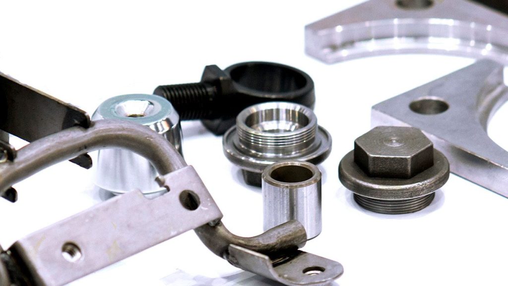
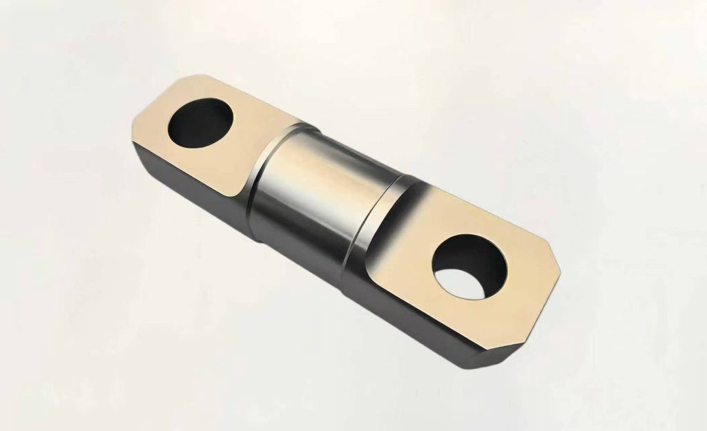
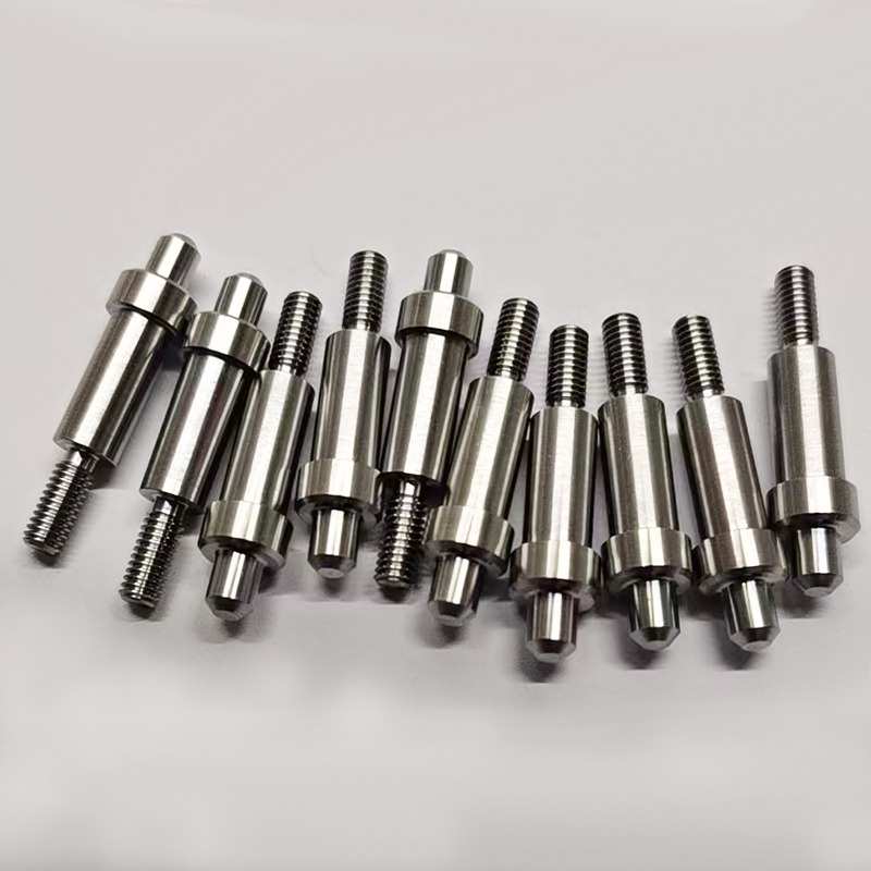
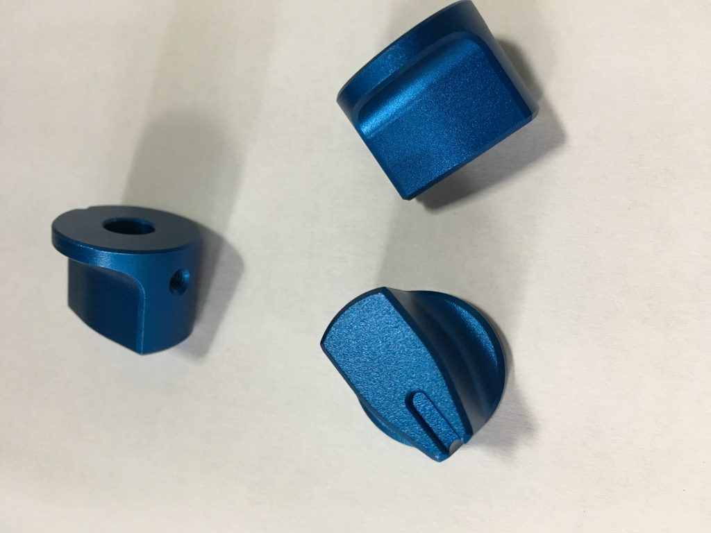
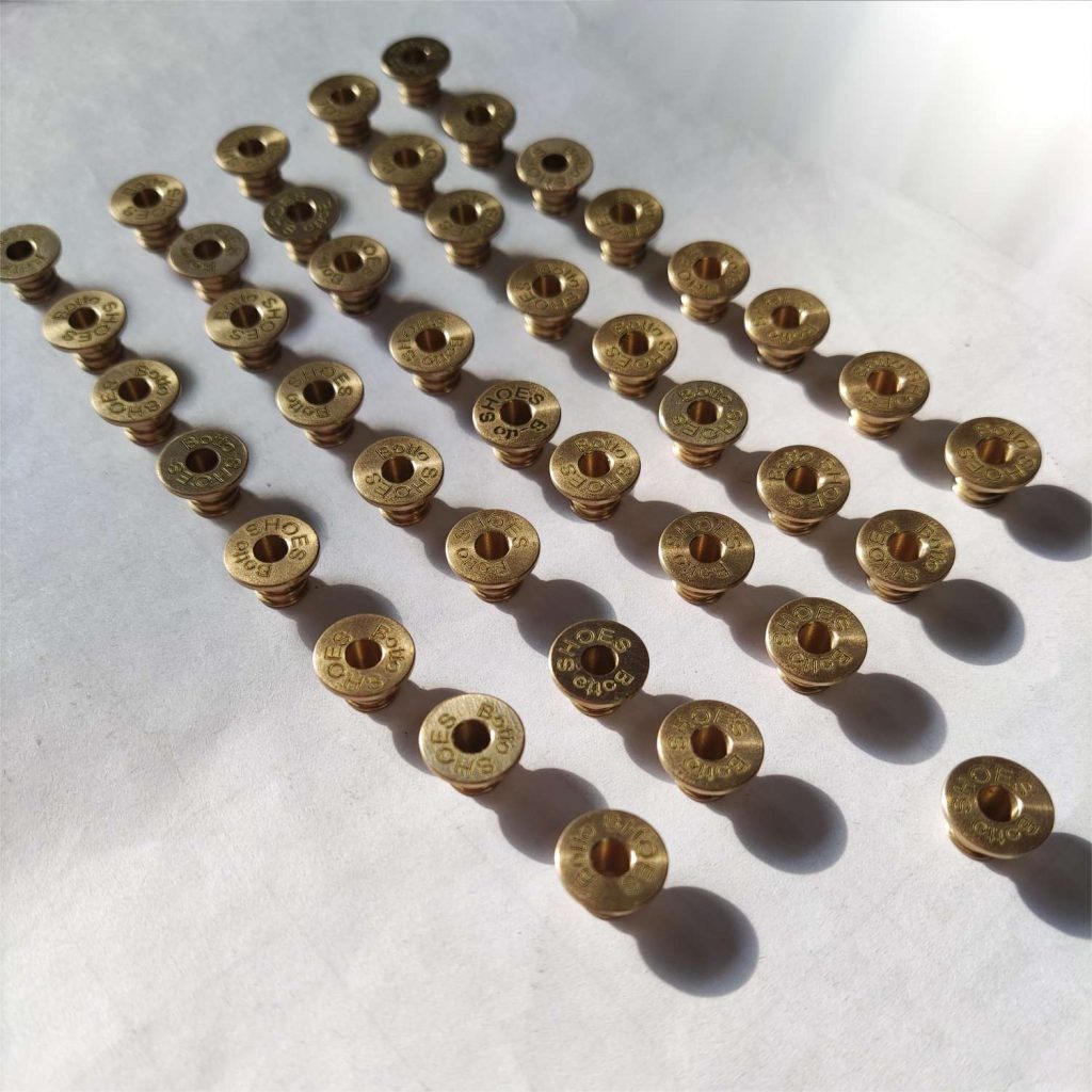
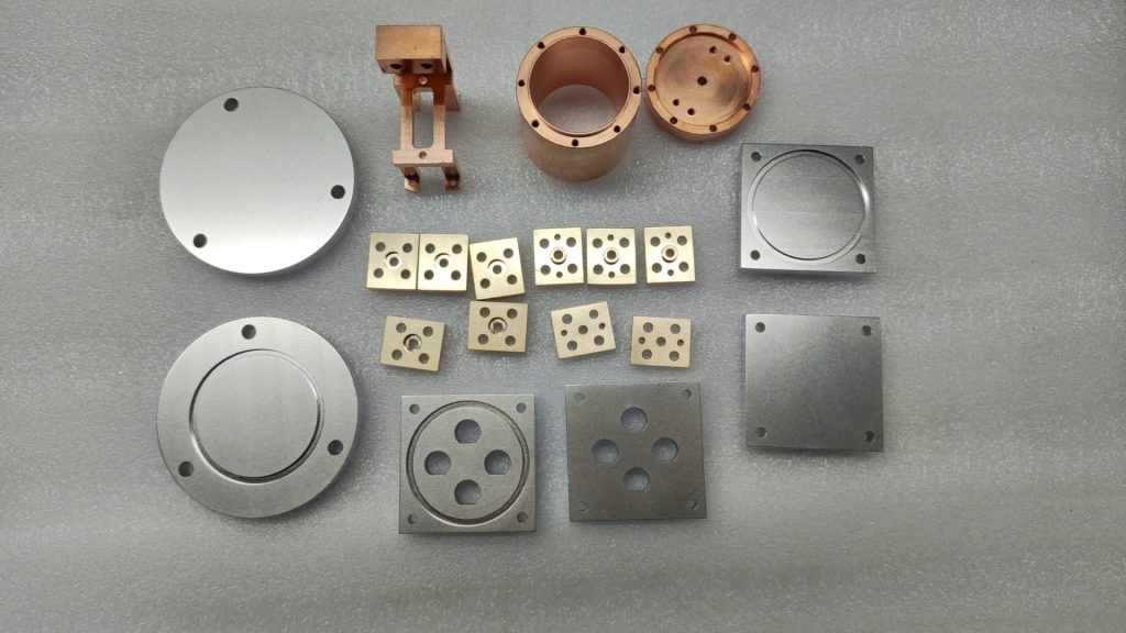
JTR Machine’s CNC turning capabilities cover aluminum alloys (Al6061/Al7075, etc.), stainless steel (304L/316L, etc.), titanium alloys (TC4, etc.), copper alloys, and various engineering plastics.
Summary & Practical Advice
There’s no one-size-fits-all solution for CNC turning chip breaking. Chipbreaker selection, cutting parameter optimization, high-pressure coolant, and programmed chip breaking – each has its strengths, and in practice you’ll often need to combine multiple approaches.
Practical advice for process engineers:
- Start with the chipbreaker – lowest cost, most stable results. First confirm whether your current insert’s chipbreaker profile matches your material and parameters.
- For stainless and titanium, prioritize high-pressure coolant – if your equipment supports it, this is the most effective way to handle difficult-to-break materials.
- For lights-out scenarios, prioritize programmed chip breaking – LFV or system chip breaking commands give you reliable results without hardware additions.
- Be careful with vibration chip breaking on finishing passes – chip breaking and surface finish can be at odds; you need to balance them.
If chip tangling is giving you headaches, start with three quick checks: Is your insert chipbreaker the right one? Are your cutting parameters inside the chipbreaker’s operating window? Is your coolant pressure and direction optimized?
JTR Machine brings 15 years of CNC turning experience to the table, covering rapid prototyping and full-scale production, with ISO9001 and TS16949 quality certifications. Whether you’re dealing with stainless steel tangling, titanium chip breaking challenges, or chip control issues on automated lines – we’re here to help you find a solution.
Stuck on chip breaking? 👉 Contact us and send us your drawings and we’ll work out a process plan with you.