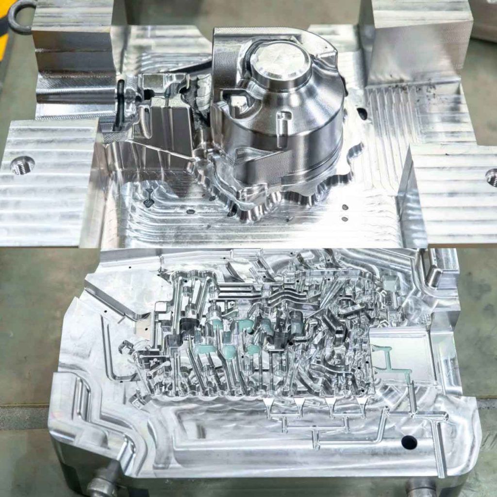
Crafting precision molds is critical for many manufacturing processes, enabling the efficient production of countless components, from consumer goods to industrial parts. For small manufacturers, factories, and companies needing custom molds, CNC aluminum offers a compelling solution due to its balance of cost, speed, and versatility. Aluminum molds are particularly well-suited for prototyping, short-run production, or parts with less abrasive materials, offering a faster and often more economical alternative to steel. However, mistakes during the manufacturing stages can lead to delays, defects, and financial losses.
Here we share common errors at various stages of CNC aluminum mold making and provide practical solutions. By understanding these challenges and implementing the straightforward solutions, you can significantly improve your mold quality, reduce manufacturing costs, and accelerate your time to market.

Pre-Production & Design Mistakes
Pre-production and design are the foundation of successful mold-making. Errors made at this stage are often the most costly to correct, as they can propagate through the entire manufacturing process. Thorough planning and communication are paramount to avoiding these early pitfalls.
Mistake 1: Insufficient Design Review & Collaboration
Rushing the design phase without proper scrutiny or failing to involve all relevant stakeholders can lead to significant problems down the line. Designs that look good on screen might not be manufacturable efficiently or even at all. This lack of foresight often results in design flaws that only become apparent during machining or, worse, during the first mold trials. The consequences can be severe, ranging from minor reworks and delays to complete mold redesigns and scrapped material, impacting both budget and timeline.
Solution:
- Implement a structured and comprehensive design review process. This isn’t a formality; it’s a critical checkpoint. Involve your design engineers, the manufacturing team (or your chosen CNC mold making service provider), and even end-users or product managers. Leverage Design for Manufacturability (DFM) principles early on. DFM means designing parts in a way that simplifies manufacturing, reduces costs, and improves quality.
- Utilize advanced CAD/CAM software for simulations, stress analysis, and mold flow analysis to identify potential issues before any metal is cut. For instance, simulating mold filling can reveal areas where plastic might short shot or experience uneven cooling, allowing for design adjustments before machining begins.
Mistake 2: Ignoring Material Selection Considerations
Choosing the wrong aluminum alloy for your mold, or simply overlooking the specific properties required for the intended application, can undermine the mold’s performance and lifespan. While aluminum is a broad category, different alloys offer distinct characteristics in terms of machinability, hardness, thermal conductivity, and wear resistance. Selecting an alloy that doesn’t match the molding material or production volume can lead to premature mold wear, inadequate heat transfer affecting cycle times, or even issues with the surface finish of the molded parts.
Solution:
Base your aluminum alloy choice on the specific demands of your project. For high-volume production with certain plastics, a harder aluminum alloy like 7075-T6 might be considered for better wear resistance, despite being tougher to machine. For general purpose or prototyping, 6061-T6 is a common choice due to its good machinability and strength. For applications demanding superior thermal conductivity, some specialized aluminum mold alloys are available.
Consult with material suppliers or experienced mold makers to understand the trade-offs. For example, if you’re molding a material with a high melt temperature, selecting an aluminum alloy with excellent thermal conductivity is crucial for efficient cooling and shorter cycle times. A common mistake we’ve seen is using standard 6061 for abrasive plastic resins, leading to mold degradation after just a few thousand cycles, when a slightly more expensive 7075 or even an anodized 6061 could have extended mold life significantly.
Here are some common aluminum alloys:
| Aluminum Alloy | Key Characteristics | Typical Applications | Considerations |
| 6061-T6 | Good machinability, weldability, strength, corrosion resistance. | General purpose molds, prototypes, low-to-medium volume production. | Balanced properties, widely available. |
| 7075-T6 | Very high strength, good fatigue resistance. | Molds for engineering plastics, higher volume applications where wear is a concern. | Less machinable than 6061, higher cost. |
| Aluminum Tooling Plate (e.g., Alca 5, MIC 6) | Excellent dimensional stability, stress-relieved, very flat. | Molds requiring high precision, often for prototype or short-run injection molding. | Specifically designed for tooling, may have lower strength than 6061/7075. |
Mistake 3: Lack of Proper Tolerancing and Surface Finish Specification
Vague or absent specifications for critical dimensions, tolerances, and surface finishes leave too much to interpretation during the machining process. This ambiguity can result in components that don’t fit together correctly, molded parts with an unacceptable aesthetic quality, or the need for extensive post-machining work to meet requirements. Without clear guidelines, even the most skilled machinist might produce a mold that is technically “accurate” but functionally flawed for its intended purpose.
Solution:
Clearly define all critical dimensions with appropriate tolerances. Use industry standards like ISO or ASME for geometric dimensioning and tolerancing (GD&T) to communicate design intent precisely. For surface finish, specify roughness average (Ra) values or other relevant parameters based on the final molded part’s functional and aesthetic needs.
For example, if a molded part requires a smooth, glossy finish, the mold cavity will need to be polished to a mirror-like finish (e.g., Ra < 0.1 µm). Conversely, if the part requires a textured or matte finish, the mold can be left with a machined surface or textured via EDM or sandblasting.
Explicitly communicate these specifications on your technical drawings and 3D models. Remember that tighter tolerances and finer surface finishes generally incur higher machining costs and longer lead times.
Mistake 4: Lack of Prototyping
Jumping straight from a theoretical design to a production-ready aluminum mold without intermediate prototyping is a significant risk. Designs, no matter how well-conceived in CAD, often reveal unexpected issues when translated into a physical part. These issues can include incorrect part fit, mold filling problems, part ejection difficulties, or even subtle aesthetic flaws. Discovering these problems after the final mold is cut can lead to incredibly expensive and time-consuming rework, potentially delaying product launch and impacting budget.
Solution:
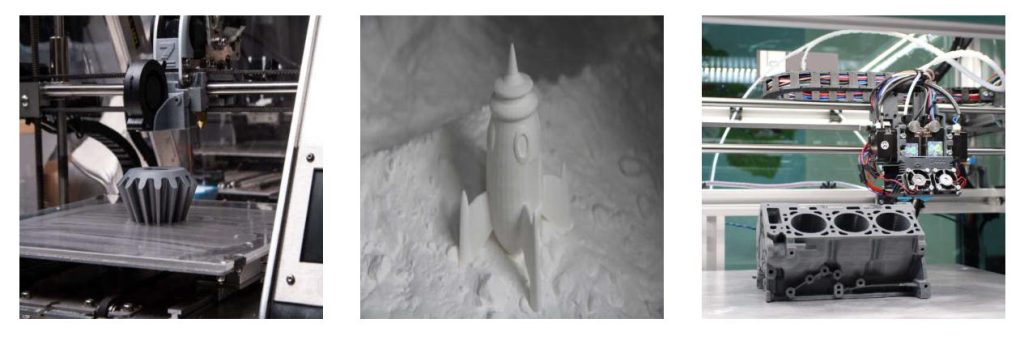
Embrace prototyping as a crucial step in the mold development process.
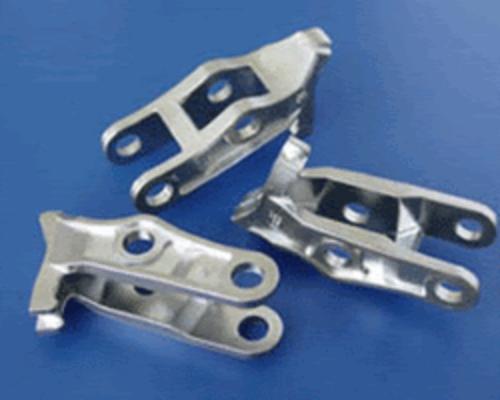
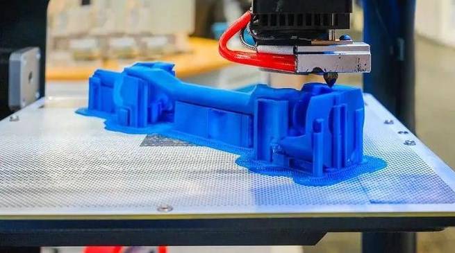
For many parts, 3D printing offers a fast and cost-effective way to create physical prototypes. This allows you to verify form, fit, and basic function. For example, a 3D-printed prototype can quickly confirm if mating components assemble correctly or if the ergonomics of a handle are comfortable.
For more functional or material-specific testing, soft tooling or rapid injection molding services can produce low-volume runs of actual molded parts using the intended production material. This allows you to test moldability, part shrinkage (and adjust the mold design accordingly), ejection mechanisms, and cooling efficiency on a smaller scale before committing to the final aluminum production mold. While it adds a step, prototyping dramatically reduces the risk of costly errors during the final mold manufacturing phase.
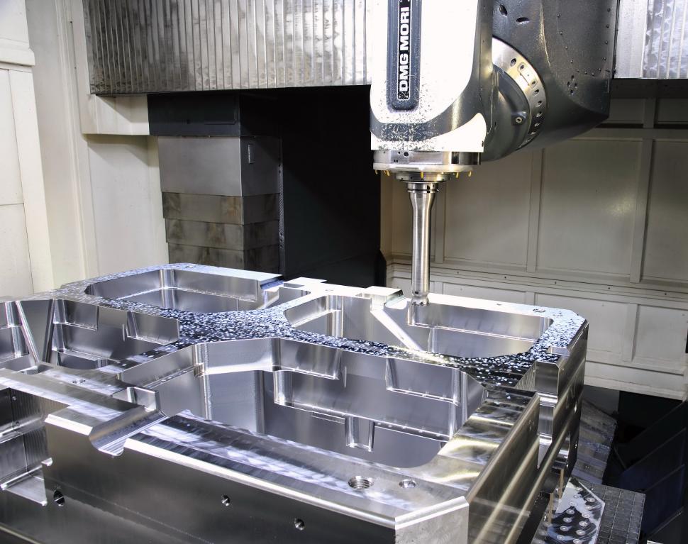
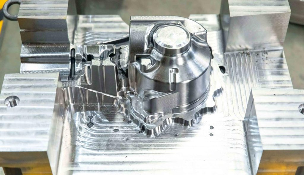
Machining & Production Mistakes
Even with a perfect design, the actual machining process presents its own set of challenges. The quality of the final aluminum mold heavily depends on precise execution, proper tooling, and careful monitoring during CNC operations. Overlooking critical aspects of the machining process can lead to compromised mold integrity and costly rework.
Mistake 1: Inadequate Tooling Selection and Management
Using the wrong type of cutting tool, continuing to operate with worn tools, or employing incorrect cutting parameters (speeds, feeds, depth of cut) are common culprits behind poor mold quality. Aluminum, while relatively soft, can be abrasive, and improper tooling leads to issues such as poor surface finishes, premature tool wear, tool breakage, and inaccurate features on the mold. This not only affects the mold itself but also increases overall production costs due to consumables and downtime.
Solution:
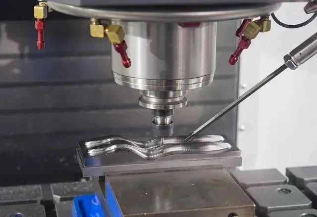
Select cutting tools specifically designed for machining aluminum. These often have specialized geometries, coatings, and flute counts to manage chip evacuation and prevent material adhesion. Implement a rigorous tool inspection and replacement schedule based on tool wear. For instance, carbide end mills are generally preferred for aluminum due to their hardness and ability to maintain a sharp edge.
Optimize cutting speeds (RPM), feed rates (inches/minute), and depth of cut to suit the specific aluminum alloy and tool type. For roughing, higher depths of cut and moderate speeds are often used, while finishing passes require lighter cuts and higher speeds to achieve desired surface finishes. Always use ample coolant or lubricant to manage heat, evacuate chips, and extend tool life.
Here is an example: A manufacturer consistently experienced poor surface finish and excessive tool wear when using general-purpose end mills for intricate aluminum mold cavities. Switching to specific high-helix, polished-flute aluminum-specific end mills dramatically improved surface finish and reduced tool consumption by 30%.
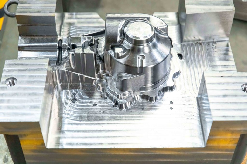
Mistake 2: Poor Fixturing and Workholding
Insufficiently securing the aluminum workpiece to the CNC machine table is a direct path to compromised accuracy and safety. If the blank vibrates, shifts, or chatters during machining, the result will be inaccurate cuts, poor surface finish, and potentially dangerous tool breakage. A stable workholding setup is foundational to precision machining.
Solution:
Design or select robust fixtures that provide maximum rigidity and stability. This might involve custom clamps, toe clamps, or high-quality vises. Ensure the workpiece is securely clamped from multiple points to minimize vibration.
For complex geometries, consider using multiple setups, but ensure precise re-registration between each setup. Vacuum chucks can be effective for thin plates, while custom jigs can support irregularly shaped blanks. Always double-check workholding before initiating any machining operation.
Mistake 3: Neglecting Thermal Management During Machining
CNC machining generates significant heat, especially in operations involving high material removal rates. If this heat is not properly managed, it can lead to thermal expansion of the aluminum workpiece, resulting in dimensional inaccuracies. Excessive heat can also accelerate tool wear, degrade surface finish, and even cause localized material changes in the mold.
Solution:
Employ effective cooling strategies. Flood coolant is common and highly effective for dissipating heat, lubricating the cut, and flushing away chips. For some applications, mist coolants or minimum quantity lubrication (MQL) systems offer environmentally friendlier alternatives while still providing necessary cooling.
Optimize cutting parameters to reduce heat generation; sometimes, a slightly lower chip load or a higher feed rate can surprisingly reduce heat by allowing chips to carry away more heat. Consider air blasting for dry machining or supplementing coolant for chip evacuation, especially in deep pockets. In situations requiring extremely tight tolerances, allowing the workpiece to cool to ambient temperature between critical finishing passes can prevent thermal distortion.
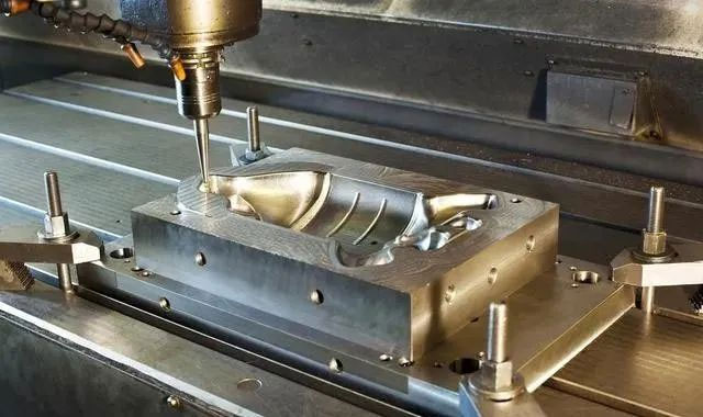
Mistake 4: Incorrect CAM Programming & Simulation
Errors in Computer-Aided Manufacturing (CAM) programming, such as incorrect toolpath generation, overlooked collisions, or suboptimal machining strategies, can lead to costly mistakes. These can range from minor surface imperfections to catastrophic machine crashes, resulting in tool breakage, scrapped material, and significant downtime. An unverified CAM program is a major risk.
Solution:
Utilize robust CAM software with comprehensive simulation and collision detection capabilities. Before any metal is cut, meticulously verify the entire toolpath in the software. Perform “dry runs” or “air cuts” on the CNC machine, where the tool runs through the program above the workpiece (or with no workpiece present) to visually confirm clearances and movements. Pay close attention to entry and exit points, ramp angles, and step-overs.
Apply different machining strategies effectively: use roughing strategies for bulk material removal and finishing strategies for achieving dimensional accuracy and surface quality. For example, high-speed machining (HSM) techniques often employ smaller depths of cut with higher feed rates to maintain consistent tool engagement and reduce cycle times while improving surface finish.
Post-Production & Quality Control Mistakes
The journey of an aluminum mold doesn’t end when it comes off the CNC machine. The final stages of finishing, inspection, and maintenance are equally crucial to ensuring the mold’s performance, longevity, and the quality of the parts it produces. Neglecting these steps can undo all the precision achieved in earlier stages.
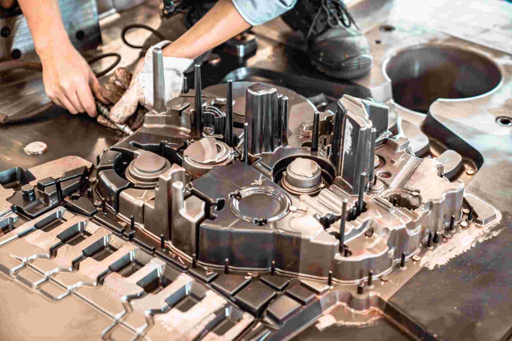
Mistake 1: Inadequate Post-Machining Finishing
Rushing or neglecting necessary deburring, polishing, or applying appropriate surface treatments can severely impact the mold’s functionality and the quality of the molded parts. Sharp edges can cause part sticking or wear on the mold, while a rough cavity surface will transfer to the molded part, affecting aesthetics and release. Without proper finishing, the mold’s lifespan can also be significantly reduced.
Solution:
Implement precise deburring techniques to remove all burrs and sharp edges that could interfere with part ejection or cause wear. Understand the specific surface finish requirements for the mold cavity based on the desired finish of the molded part. For clear or highly aesthetic parts, the mold cavity may require meticulous polishing, often in multiple stages with progressively finer abrasives, to achieve a mirror-like finish.
For some applications, surface treatments like hard anodizing can significantly increase the surface hardness and wear resistance of aluminum molds, extending their operational life, especially when molding abrasive materials or for higher production volumes. For instance, a hard anodized 6061 aluminum mold can exhibit wear resistance comparable to certain steels for short-run applications, delaying the need for steel tooling.
Mistake 2: Skipping or Incomplete Quality Control Checks
Failing to conduct thorough quality control checks at every stage, but especially on the finished mold, is a direct route to producing faulty components and incurring significant costs. Without verifying dimensions, surface quality, and functionality, you risk launching production with a mold that produces out-of-spec parts, leading to costly reworks, wasted material, and damage to your reputation.
Solution:
Establish and adhere to comprehensive Quality Control (QC) protocols. This includes dimensional inspection using precision tools like Coordinate Measuring Machines (CMMs) for critical features, digital calipers, micrometers, and optical comparators. Conduct visual inspections for surface defects, tool marks, or inconsistencies.
Crucially, perform trial runs, often referred to as T1 samples (first shots), with the intended molding material. During this phase, meticulously evaluate:
- Part Dimensions: Use CMM or optical scanning to verify all critical dimensions against your part specifications, accounting for material shrinkage.
- Part Aesthetics and Functionality: Inspect for surface finish issues, sink marks, flash, warpage, or any other visual defects. Confirm that the part fits correctly with other components and performs its intended function.
- Mold Performance: Observe mold filling, cooling efficiency, and part ejection. Ensure cycle times are consistent and within expected parameters.
- Material Compatibility: Verify that the molded part exhibits the desired material properties (e.g., strength, flexibility, color).
Evaluate the molded parts against design specifications and make necessary adjustments to the mold or molding process.
Partnering with CNC Mold Making Services
Why Choose Professional Services?
For small manufacturers and factories, working with experienced CNC mold-making services like JTR Machinery offers multiple advantages:
- Expertise and Precision: JTR Machinery utilizes advanced CNC machines and skilled engineers to produce molds with unmatched accuracy.
- Cost and Time Efficiency: Outsourcing eliminates the need for expensive equipment and reduces production timelines.
- Comprehensive Solutions: From material selection to post-production finishing, JTR Machinery provides end-to-end mold-making services tailored to your requirements.
Partner with JTR Machinery for your CNC aluminum mold-making needs. With our commitment to quality and precision, we ensure your projects are completed on time and to the highest standards. Contact us today to discuss your custom mold requirements and get a free quote.