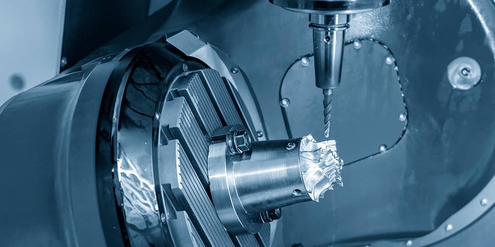
CNC machining is the primary technology used in modern production to produce high-precision, consistent products. Dimensional tolerance is a key aspect in determining part quality. How we manage these tolerances has a direct impact on the size accuracy, assembly fit, and overall performance of the parts. Furthermore, it has a substantial impact on manufacturing costs and productivity. As a result, the ability to control tolerances consistently and reliably is a fundamental talent that every CNC machining company and engineer must possess. In this post, we will look at how to effectively control tolerances during the CNC machining process.
Part 1. Getting Tolerance Right: The First Step in Control
When it comes to determining control in a tolerance, it begins not in the machine but in the design. Most accuracy issues can be tied back to setting tolerances too tightly or too unreasonably in the first place.
1. Design for Function, Not Just to Minimize
Setting tolerances just for the sake of setting them to a tighter number isn’t a good approach. Tighter tolerances can lead to alignment issues, increased costs, additional time for machining, and more complications. As a base guideline, the following tolerances can be used so long as they’re guided by serving a specific design function:
– General mechanical parts: ±0.05 mm
– Precision functions: ±0.01–0.02 mm
– Ultra-precision function in molds: ±0.005 mm or even less
Excessive specification of precision, for example, ±0.005 mm on a support bracket, only serves to increase costs and complicate the tolerances without adding value to serving the function of the product.
2. Choosing the Right Tolerance Level
For CNC machining, the following tolerances can be expected, separated by each machining function to be performed:
– Standard milling: ±0.05 mm
– Precision milling: ±0.02 mm
– High precision: ±0.005–0.01 mm
– Mold grade: ±0.002–0.005 mm
Setting reasonable design tolerances from the beginning streamlines the remainder of processes needed while keeping in mind that there is a set of tolerances that need to be controlled.
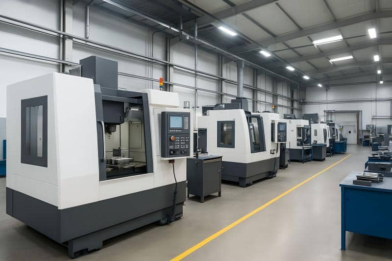
Part 2: Equipment and Environment: The Foundation of Accuracy
1. Machine Accuracy Determines the Upper Limit
Poor equipment will always result in unsatisfactory results, and no machining strategy will solve that issue. The most important factors in machines are:
– Spindle runout
– Ball screw preloading and backlash
– Guideway rigidity and straightness
– Thermal compensation systems
– Repeatable positioning accuracy
As you go to higher-end machines, these factors will be reduced, and thermal control will be added—very important for tight tolerances.
2. Temperature Control: A Major Source of Dimensional Drift
Heat will make metal expand. For instance, the expansion of steel when the temperature is increased by about 10 degrees Celsius is several microns. Deviations of this order can quickly cause you to exceed the tolerances.
You can control the temperature by:
– Keeping the shop floor at 20±1°C. This is sometimes referred to as the comfort zone.
– Preheating machines for about 20–40 minutes.
– Using active thermal systems.
– Measuring parts while they are running.
To ensure the best results, many precision machining companies have fully climate-controlled workshops.
Part 3. Tooling: Directly Influencing Dimensional Accuracy
As the part-contacting component, tool condition has an immediate impact on tolerance.
1. Use High-Quality Cutting Tools
Premium tools offer better cutting stability and slower wear, such as:
- Carbide tools
- Nano-coated tools (TiAlN, TiCN, etc.)
- Ultra-sharp fine-grind edges
Stable tools ensure consistent part geometry.
2. Control Tool Wear
Tool wear causes dimensions to drift—typically resulting in oversized parts due to increased cutting pressure.
Good practices include:
- Setting tool life management thresholds
- Using tool-breakage/wear monitoring systems
- Adjusting tool offsets based on real measurements
3. Apply Tool Offsets Correctly
Tool length and radius compensation are vital for maintaining dimensional consistency, especially in batch production.
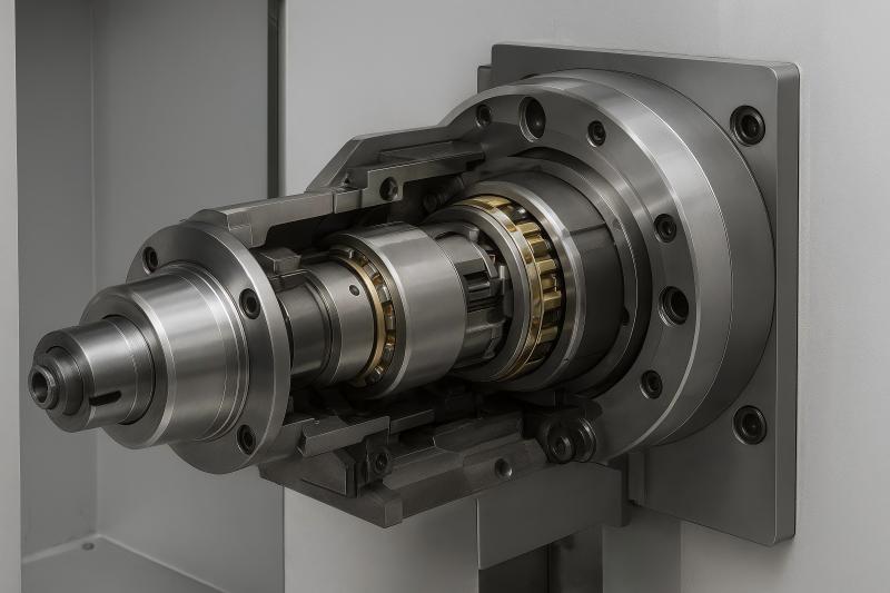
Part 4. Fixturing: Stable Clamping for Stable Accuracy
1. Precision Fixtures Improve Locational Consistency
Common precision fixtures include:
- High-accuracy vises
- Fixture plates
- Locating pin and hole systems
- Vacuum fixtures for thin workpieces
Better fixturing leads to higher repeatability across multiple parts.
2. Avoid Clamping Deformation
Thin-wall parts or plastics deform easily under excessive clamping force. After unclamping, elastic recovery can cause dimensional errors.
Solutions include:
- Soft jaws
- V-blocks or custom fixtures
- Multi-point balanced clamping
- Vacuum clamping
A well-designed fixture boosts both precision and yield rates.
Part 5. Machining Strategies: Roughing–Finishing Separation
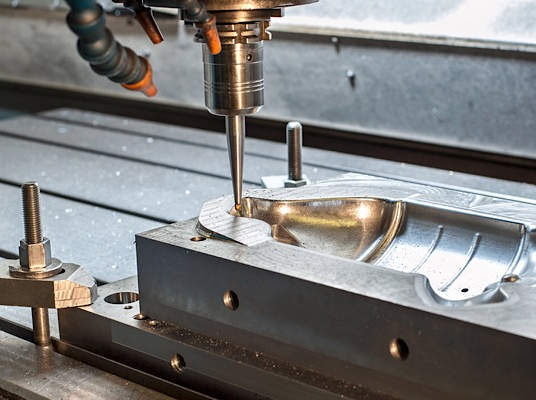
1. Separate Roughing and Finishing
Roughing removes most of the material but induces heat and vibration. Leaving a 0.2–0.5 mm allowance for finishing helps ensure that final dimensions remain accurate.
2. Use Light Cuts for Finishing
Finishing should use:
- Shallow depth of cut (0.1–0.3 mm)
- Low feed rate
- High spindle speed
- Consistent toolpaths
This improves dimensional repeatability and surface quality.
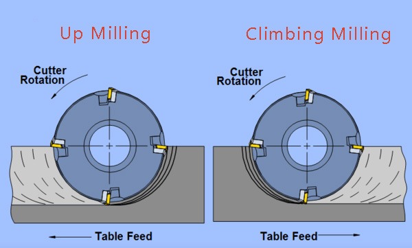
3. One-Direction Cutting to Reduce Backlash Errors
Since ball screws exhibit some backlash, unidirectional finishing avoids errors caused by direction changes.
4. Use Machine Compensation Features
High-precision operations should utilize:
- Ball screw error compensation
- Spindle thermal compensation
- Tool thermal compensation
- Servo dynamic error compensation
These digital tools help maintain dimensional accuracy throughout the machining cycle.

Part 6. Measurement and Quality Control
1. In-Process Measurement
Using a machine probe (e.g., Renishaw), the operator can automatically measure:
- Workpiece position
- Critical dimensions
- Tool wear
Probes create a closed feedback loop that maintains tolerances during machining.
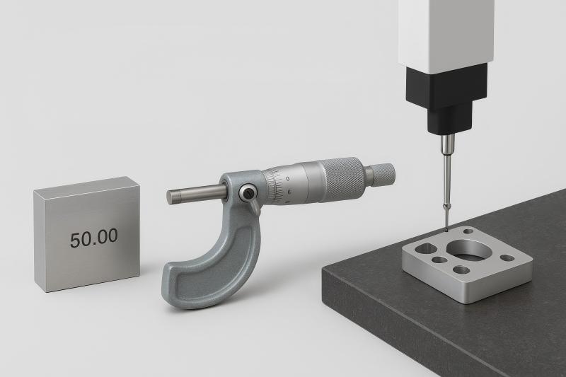
2. Post-Measurement for Final Verification
Common tools include:
- Vernier calipers and micrometers
- Plug and ring gauges
- Coordinate Measuring Machines (CMM)
- Optical measurement systems
CMMs are often the gold standard for high-precision components.
3. Statistical Process Control (SPC)
SPC helps track trends such as:
- Dimensional drift
- Tool wear patterns
- Positioning inconsistencies
This prevents large-scale scrap, especially in mass production.
Part 7. Material Characteristics and Their Impact on Tolerance
Different machining materials react in their own way when you’re cutting them or when the temperature changes, and that really affects how accurate your machining can be.
- Aluminum (like 6061): Has a high thermal expansion coefficient needing careful management of machining temperature and cutting heat.
- Stainless steel (like 304 and 316): Has a tendency to work harden and accelerate tool wear requiring sharper tools and more conservative cutting feed speeds.
- Titanium alloys: Have low thermal conductivity, which causes high temperatures at the tool tip and quick wear of cutting tools. Managing vibrations and heat is crucial as well.
- Plastics: They have a high coefficient of thermal expansion and are prone to deformation under tool pressure. Usually, light cutting and high-speed cutting are required.
To wrap up, controlling tolerance for CNC machining isn’t just one thing; it’s an entire system working together. Tolerance control amalgamates machine tool capability, tooling selection, work holding design, machining strategy, measurement (metrology), and control of the machining environment. To modify control features of the CNC machine, one must understand the control system design principles of tolerance and the CNC system. Designing technically feasible ratios of tolerances, providing control equipment with temperature control (if needed), effective tool change, stable fixturing, control of the CNC machining process, measurement with feedback, and control of different strategies with different machining materials are fundamental. If enterprises control all synergistic processes together, they can improve tolerance consistency and decrease costs significantly. Thereby enhancing their competitive position in the market.