


If you’ve ever seen a polished metal shaft, a precision threaded connector, or a tiny bone screw used in medical devices, chances are they were made using CNC turning. In simple terms, it’s a machining process where the workpiece rotates and the cutting tool moves along its surface to remove material. Unlike milling, where the tool moves around a stationary part, turning flips the script: the part spins, the tool feeds in. That makes it ideal for round, cylindrical, conical, and other rotationally symmetric shapes.
This guide covers the basics—from machining steps and machine components to common operations, material selection, tolerance control, common defects, and how CNC turning differs from CNC milling. It’s written in practical, plain language, the way engineers talk on the shop floor.
What Is CNC Turning?
CNC turning is a subtractive manufacturing process. The machine grips the workpiece and rotates it at high speed while a cutting tool follows a programmed path, removing excess material until the desired shape remains. Because the entire process is controlled by a computer numerical control (CNC) system, repeatability and consistency far exceed what manual lathes can achieve.
Compared to traditional manual turning, CNC turning offers several clear advantages:
- No dependence on a machinist’s “feel.” The program defines the toolpath, so every part comes out nearly identical.
- Multiple operations in one setup. Facing, turning, threading, grooving, and drilling can all be done in sequence without moving the part.
- Tighter and more stable tolerances. A manual lathe might hold ±0.05 mm on a good day; a CNC lathe easily achieves ±0.01 mm, often less.
Of course, CNC turning isn’t for everything. If your part is a rectangular housing or has complex 3D contours, CNC milling is usually the better choice. More on that later.
JTR provides precision CNC turning services for prototypes and production runs.
How CNC Turning Works, Step by Step
Regardless of complexity, most turning jobs follow four basic steps: programming, setup, machining, and inspection.
Programming
This is where you tell the machine what to make. Engineers import the 3D model into CAM software, define toolpaths, cutting speeds, feed rates, depth of cut, and other parameters, then generate G-code. Common G-code commands include G00 (rapid positioning), G01 (linear interpolation), G96 (constant surface speed), and G97 (constant spindle speed).
Programming also involves decisions like:
- Tool nose radius compensation (G41/G42). The insert tip isn’t perfectly sharp. Without compensation, tapers and arcs will have errors.
- Chip breaker selection. Stainless steel, aluminum, and titanium produce different chip forms. If chips don’t break well, they can wrap around the tool and scratch the surface.
- Separate roughing and finishing passes. Roughing uses larger depths of cut for speed; finishing uses light cuts for better surface quality.
For example, when turning 304 stainless steel shafts, we typically control roughing depth at 1–2 mm and finishing depth at 0.1–0.3 mm. This balances efficiency with a clean surface finish.
Setup
After programming, the raw workpiece is mounted on the lathe spindle. Common workholding options include:
- Three-jaw chuck: Most versatile, good for round bar stock.
- Collet chuck: Higher precision, ideal for small-diameter parts with consistent diameters.
- Tailstock with live center: Supports long shafts to prevent deflection during cutting.
Tool offset calibration is critical at this stage. If the machine doesn’t know exactly where the tool tip is, every dimension will be off. Many shops perform a first-article trial cut: machine a short section, measure it, and adjust tool offsets as needed.
Machining
The workpiece rotates and the tool feeds along its path, removing material in controlled layers. Key parameters include:
- Cutting speed (m/min): Varies widely by material.
- Feed rate (mm/rev): How far the tool advances per revolution.
- Depth of cut (mm): How much material is removed in one pass.
Coolant also plays a big role—not just for cooling but also for lubrication and chip evacuation. When cutting stainless steel or titanium, insufficient coolant can destroy an insert in seconds. In our shop, coolant runs constantly during continuous operations.
Inspection
After machining, parts are measured for dimensions and surface finish. Common tools include:
- Micrometers and calipers: For outer diameters and lengths.
- Bore gauges: For internal diameters.
- Surface roughness testers: To measure Ra values.
- Coordinate measuring machines (CMMs): For complex or tight-tolerance parts.
A proper shop performs first article inspection (FAI) and periodic in-process checks. If dimensional drift is detected, tool offsets are corrected or inserts replaced before parts go out of spec.
Main Components of a CNC Lathe
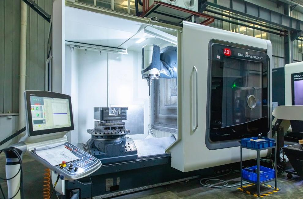
A typical CNC lathe consists of these key components. Understanding them helps you evaluate machine capability and expected quality.
| Component | Function | Impact on Accuracy |
| Headstock | Holds the spindle that rotates the workpiece | Spindle radial runout directly affects roundness |
| Chuck | Grips the workpiece | Uneven clamping force can cause distortion |
| Turret | Holds multiple tools and changes them automatically | Turret repeatability affects batch consistency |
| Tool Post | Secures a single cutting tool (common on manual lathes) | On CNC lathes, turrets are more common |
| Tailstock | Supports long workpieces with a center or live tool | Tailstock alignment affects cylindricity of long shafts |
| Control Panel | Inputs G-code and monitors operation | Program errors directly affect machining results |
| Coolant System | Cools, lubricates, and removes chips | Poor cooling causes thermal deformation and tool wear |
Many high-precision lathes hold spindle runout within 0.002 mm. That number may seem small, but it matters a lot when you’re turning a slender shaft.
Common CNC Turning Operations
CNC lathes can perform a wide range of cutting actions. Here are the most common ones.
| Operation | Description | Typical Parts |
| Facing | Flattens the end of the workpiece | Flanges, shaft ends |
| OD Turning | Machines the outer diameter to final size | Drive shafts, pins |
| Boring | Enlarges or finishes internal diameters | Bearing housings, sleeves |
| Drilling | Creates holes along the axis | Center oil holes in shafts |
| Taper Turning | Cuts conical surfaces | Pipe fittings, tapered shanks |
| Grooving | Cuts narrow channels | O-ring grooves, relief grooves |
| Threading | Produces internal or external threads | Fasteners, connectors |
| Knurling | Creates a textured grip pattern | Knobs, handles |
In practice, most turned parts require multiple operations. A shaft might need facing, center drilling, OD turning, grooving, and threading—all completed in one setup on a CNC lathe. This eliminates the alignment errors caused by repeated clamping.
Material Selection and Machinability
CNC turning works with a wide range of materials, from aluminum and brass to stainless steel, titanium, and even engineering plastics. But each material has its own personality. Choosing the right one isn’t just about strength—it’s also about how easily it can be machined.
Here’s a comparison of common turning materials.
| Material | Machinability | Typical Cutting Speed (m/min) | Common Issues |
| Aluminum 6061 | Excellent | 200–350 | Burr formation, built-up edge |
| Brass C360 | Excellent | 150–250 | Short chips, easy to clean |
| Stainless 304 | Fair | 60–120 | Work hardening, tool wear |
| Stainless 316 | Poor | 50–100 | Sticky, needs sharp inserts |
| Titanium Ti-6Al-4V | Poor | 30–60 | Poor thermal conductivity, high tool tip temperature |
| PEEK | Good | 50–100 | Melts at high speeds |
Aluminum 6061 is one of the easiest materials to turn. Cutting speeds can be high and surface finishes are easy to achieve. The downside is a tendency to form a built-up edge—a layer of aluminum that sticks to the insert and causes dimensional drift. That’s why we often use polished carbide inserts with plenty of coolant.
Stainless 304/316 is common in medical and food equipment, but it work-hardens quickly. If you take too shallow a cut or feed too slowly, the surface gets harder and more difficult to machine. It’s better to cut with a healthy chip load—don’t rub.
Titanium is notoriously difficult. Its low thermal conductivity concentrates heat at the cutting edge, wearing out inserts fast. You generally need lower cutting speeds, high-pressure coolant, and sometimes specially coated tools.
PEEK, POM, and similar plastics have low melting points. Running too fast can melt the surface or cause fuzzing. Sharp tools, light cuts, and higher feed rates help move heat away.
If you’re unsure about material selection, JTR engineers can suggest a suitable material and heat treatment based on your drawing before machining begins.
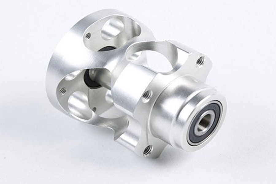
Tolerances, Surface Finish, and Quality Control
The two numbers people ask about most are tolerance and surface roughness. How precise can CNC turning be? The answer depends on the machine, tooling, material, and batch size.
Common Tolerance Grades
According to ISO 286, tolerances are expressed as IT grades. Standard CNC turning typically achieves:
- IT7–IT8: For general fits, like bushings and bracket holes.
- IT6: For precision shafts and bearing seats. On a 20 mm diameter, this means roughly ±0.006 mm.
- IT5 or better: Requires special process control, such as temperature-controlled rooms and secondary finishing.
If a drawing doesn’t specify tolerances for certain dimensions, ISO 2768-1 can be applied. But critical dimensions should always be marked clearly—otherwise, suppliers will machine to a medium accuracy level.
Surface Roughness Ra
Surface roughness is often expressed as Ra in micrometers. Typical CNC turning ranges:
- Rough turning: Ra 3.2–6.3 μm
- Semi-finishing: Ra 1.6–3.2 μm
- Finish turning: Ra 0.8–1.6 μm
- Mirror finish: Ra < 0.4 μm, usually requires grinding or polishing
Note: Ra is an average and doesn’t fully capture deep scratches or waviness. For sealing surfaces, Rz and waviness should also be considered.
Quality Control Process
JTR follows a structured quality assurance process for turned parts. It includes several stages:
- Material incoming inspection: Verify grade and hardness before machining.
- First article inspection (FAI): Full dimensional report using CMM.
- In-process control: IPQC routine patrol and SPC monitoring to catch drift early.
- Final outgoing inspection: AQL sampling or 100% inspection, depending on customer requirements.
- Certificate pack: Includes dimensional report, material certificate, and surface treatment report.
Core inspection equipment:
- Hexagon CMM: High-precision 3D measurement for complex geometries (±0.0025 mm resolution).
- Optical comparator / 2.5D: Fast profile measurement.
- Hardness tester: Rockwell & Brinell.
CNC Turning vs CNC Milling: How to Choose?
This is often the first question clients ask: should my part be turned or milled?
The simplest way to decide is to look at the shape.
- Round, symmetrical parts—shafts, sleeves, discs, connectors—start with CNC turning.
- Parts with flat faces, pockets, irregular contours, or 3D surfaces—CNC milling is better.
- If a part has both cylindrical features and complex side features, you may need turn-mill combination or a secondary milling operation.
| Comparison | CNC Turning | CNC Milling |
| What rotates | Workpiece | Cutting tool |
| Best for | Shafts, discs, sleeves, threaded parts | Housings, brackets, irregular shapes |
| Typical tolerance | ±0.005–0.01 mm | ±0.01–0.02 mm |
| Surface roughness | Easily achieves Ra 0.8 | Typically Ra 1.6 |
| Efficiency | Higher for rotational parts | Higher for complex flat parts |
For example, an externally threaded shaft is a natural fit for turning. A phone frame cannot be turned—it must be milled. Some parts, like power tool output shafts with both outer diameters and splines, require turning plus milling. JTR offers combined CNC milling and turning capabilities to reduce inter-process handling.
Common Turning Defects and Troubleshooting
CNC turning isn’t problem-free. Here are the most common defects and how experienced machinists address them.
| Defect | Typical Cause | Solution |
| Chatter marks on surface | Tool overhang too long, improper speed | Shorten tool, adjust cutting speed |
| Taper on outer diameter | Tailstock misalignment, worn insert | Realign tailstock, replace insert |
| Poor surface finish | Feed too high, poor chip breaking | Reduce feed, use chip breaker insert |
| Oversized or undersized dimensions | Wrong tool offset, thermal deformation | Recalibrate offsets, improve cooling |
| Thread galling or crossed threads | Encoder signal error, programming issue | Check encoder, reprogram |
Many of these defects come down to wrong parameters. Experienced operators can spot trouble early from chip color, sound, and vibration—long before parts are scrapped.
Applications of CNC Turning
CNC turning shows up in almost every manufacturing sector.
- Automotive: Transmission shafts, gear blanks, bushings, motor shafts. Demand for EV motor and reducer shafts is growing fast.
- Aerospace: Titanium fasteners, superalloy bushings, hydraulic fittings. These parts demand extreme material and tolerance control.
- Medical devices: Bone screws, dental implants, endoscope components. Many parts are only a few millimeters in size and require Swiss-type lathes.
- Consumer electronics: Knobs, connector housings, microphone parts. Small size, high volume.
- Industrial machinery: Valve cores, pump shafts, hydraulic couplings.
Many of these components are custom-turned in small to medium batches. That’s one reason overseas customers turn to China for CNC machining—cost efficiency and quick response. JTR, as a provider of CNC machining services in China, has years of experience in CNC turning in China, especially with stainless steel and aluminum precision parts.
Design Tips for CNC Turned Parts (DFM)
A few simple design rules can save you time and money when designing turned parts:
- Avoid sharp internal corners.
The insert tip has a radius. Internal corners should have an R or a relief groove, or the tool may chip.
- Keep holes reasonably shallow.
Generally, hole depth should not exceed 3–4 times the diameter. Deeper holes require slender boring bars that chatter.
- Don’t go too thin on walls.
Thin-walled parts distort easily during turning. A minimum wall thickness of 0.5 mm is advisable, depending on material. If thinner is necessary, additional support or secondary finishing may be needed.
- Use standard thread profiles when possible.
Non-standard threads require custom tooling, which increases lead time and cost.
- Allow for surface treatment.
If anodizing, plating, or heat treatment is required, note it on the drawing and leave appropriate stock on critical surfaces.
JTR provides free DFM feedback, flagging potential manufacturing issues before the job reaches the shop floor.
A Note on Swiss CNC Lathes
Swiss-type lathes deserve a quick mention.
On a standard CNC lathe, the headstock is fixed and the workpiece extends from the chuck. If the part is very long and thin—say, 2 mm in diameter and 40 mm long—it will deflect under cutting pressure. A Swiss lathe (also called a sliding headstock lathe) solves this by moving the headstock forward and backward while the workpiece passes through a guide bushing. The tool cuts right next to the bushing, so the part is always supported.
This makes Swiss lathes ideal for small-diameter precision parts in medical and electronics industries, where tolerances of ±0.005 mm or better are common. However, they are expensive machines and not every turned part needs them.
FAQ
Q: What tolerance can CNC turning achieve?
A: Standard CNC lathes can hold ±0.01 mm; precision turning can reach ±0.005 mm. It depends on part size, material, and equipment.
Q: What materials can be CNC turned?
A: Aluminum, brass, stainless steel, carbon steel, titanium, and engineering plastics like PEEK, POM, and PTFE can all be turned, but cutting parameters vary widely.
Q: What is the fundamental difference between CNC turning and CNC milling?
A: Turning rotates the workpiece while the tool feeds; milling rotates the tool while the workpiece moves. Turning suits rotational parts, milling suits flat and complex contours.
Q: What surface roughness can turned parts achieve?
A: Finish turning typically produces Ra 0.8–1.6 μm. Grinding or polishing can reduce it further.
Q: What files do I need to provide for a CNC turning quote?
A: STEP, IGES, or DWG drawings with material, tolerances, and surface finish requirements are usually sufficient.
Q: Is CNC turning suitable for prototyping?
A: Yes. Turning programs are relatively quick to generate, and single-piece prototype costs are often lower than milling.
Q: Are there reliable CNC turning suppliers in China?
A: Yes. JTR is a precision CNC machining factory in China that supports CNC turning in China orders and export business.
Conclusion
CNC turning may look simple—spin the part, feed the tool—but achieving stable tolerances, good surface finishes, and consistent batches requires the right equipment, tooling, programming, and inspection. Hopefully this guide gives you a clearer picture of how the process works.
If you have a drawing in hand, or just want to ask whether a particular part should be turned, feel free to reach out to JTR. We handle inquiries related to CNC machining service every day and are happy to give practical advice. Even if you’re not ready to order, asking costs nothing.
Next step: Explore JTR’s CNC Machining Products Cases, or upload your drawing for a quote.
Our CNC Machining Center
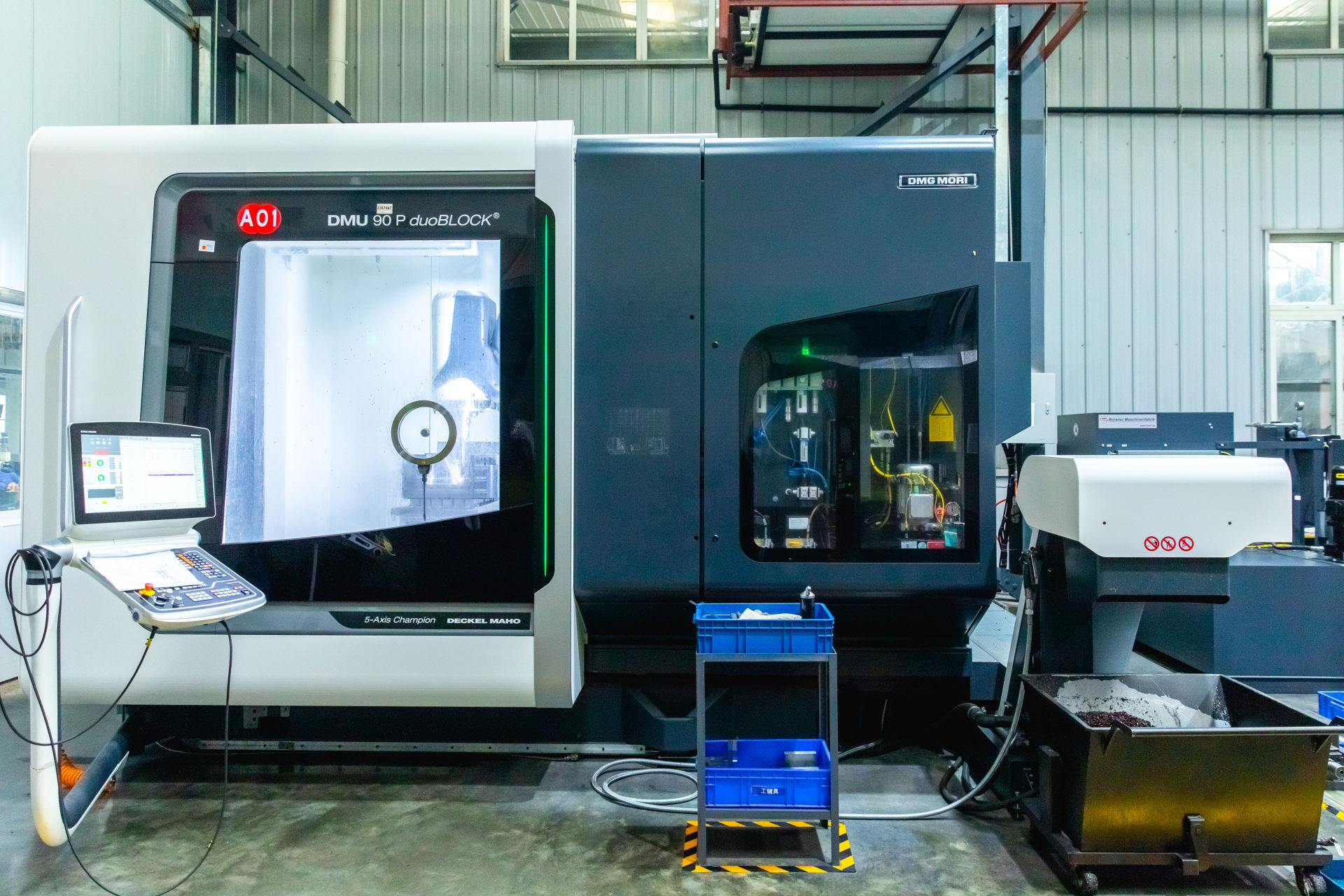
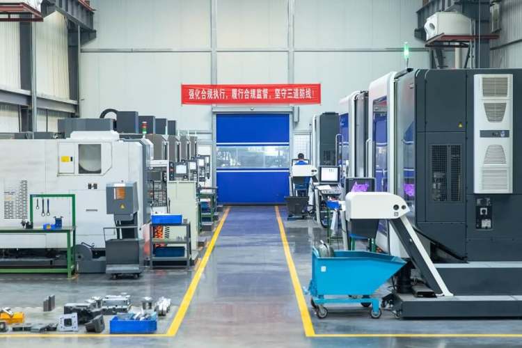
Our CNC machining center has more than 70 advanced equipment, which is equipped with 3-axis, 4-axis, and 5-axis CNC machines, able to manufacture parts that meet most requirements from customers. In addition to CNC machining centers, there are also advanced full-automatic die casting machines from 300T to 1000T with an annual capacity of million pieces of parts.