

The Reputation Problem: Why ADC12 Gets a Bad Rap
Mention ADC12 in a machining shop and you’ll often get the same reaction: a slight grimace. “High silicon. Eats tools. Gummy chips.” It’s the kind of reputation that sticks.
And there’s truth to it. ADC12 contains 9.6–12.0% silicon — hard particles that act like microscopic abrasives on cutting edges. If you compare ADC12 directly against A380, the tool wear numbers aren’t pretty: ADC12 tools wear 10–15% faster than A380 during secondary machining. That’s a real difference on a production floor.
But here’s where the story gets interesting — and where most people stop paying attention.
ADC12 is not the easiest die-cast aluminum alloy to machine. A380 holds that title with its lower silicon content. But ADC12 is easier to machine than its reputation suggests, especially when compared to low-iron alloys like A356. The iron content that many engineers worry about — up to 1.3% by weight — is actually what makes the difference.
A foundational 1965 study on Al-Si-Cu die casting alloys established this clearly: machining performance deteriorates when iron content exceeds 2%, but when iron is too low, the die itself suffers from seizing. ADC12 sits in a deliberate sweet spot — high enough iron to promote chip formation, low enough to avoid hard-spot problems.
So the question isn’t “Is ADC12 hard to machine?” It’s “Compared to what?” And once you look at the data, the answer changes.
The Chemistry Behind ADC12’s Machinability
You don’t need a metallurgy degree to understand why ADC12 machines the way it does. Three elements matter most: silicon, iron, and copper.
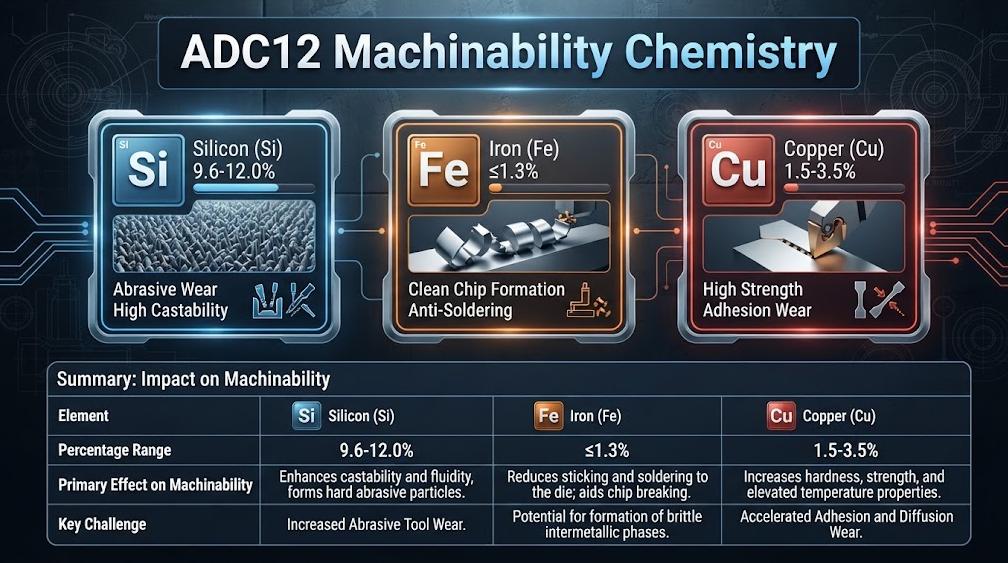
Silicon (9.6–12.0%) gives ADC12 its excellent castability — it flows into thin walls and complex geometries better than any other common die-cast aluminum alloy. But those same silicon particles are hard enough to wear down carbide tools at an accelerated rate.
Iron (≤1.3%) is the unexpected ally. It promotes clean chip formation, reducing the gummy, stringy chips that plague low-iron alloys like A356. Iron also protects the die from soldering during casting. The trade-off: iron above 2% creates brittle β-Fe phases that worsen machinability. ADC12 stays well below that threshold.
Copper (1.5–3.5%) increases strength and hardness but contributes to adhesion wear during high-speed milling. The combination of hard silicon (abrasive wear) and copper-rich matrix (adhesive wear) is what makes tool selection matter so much.
| Element | Typical Range | Effect on Machinability |
| Silicon (Si) | 9.6–12.0% | Abrasive wear on tools; improves castability and thin-wall filling |
| Iron (Fe) | ≤1.3% | Promotes chip breakage; reduces die soldering; >2% causes hard spots |
| Copper (Cu) | 1.5–3.5% | Increases strength; contributes to adhesion wear at high speeds |
| Others (Mg, Mn, Zn) | Mg ≤0.3%, Mn ≤0.5%, Zn ≤1.0% | Minor effects on machinability; contribute to mechanical properties |
Data sources: Alloy composition ranges from patent and standard references; machinability effects from published machining studies.
One more factor worth noting: ADC12’s lower casting temperature produces approximately 35% less dross than 356 secondary and A356.2 alloys. Less dross means fewer oxide inclusions that can cause hard spots during machining.
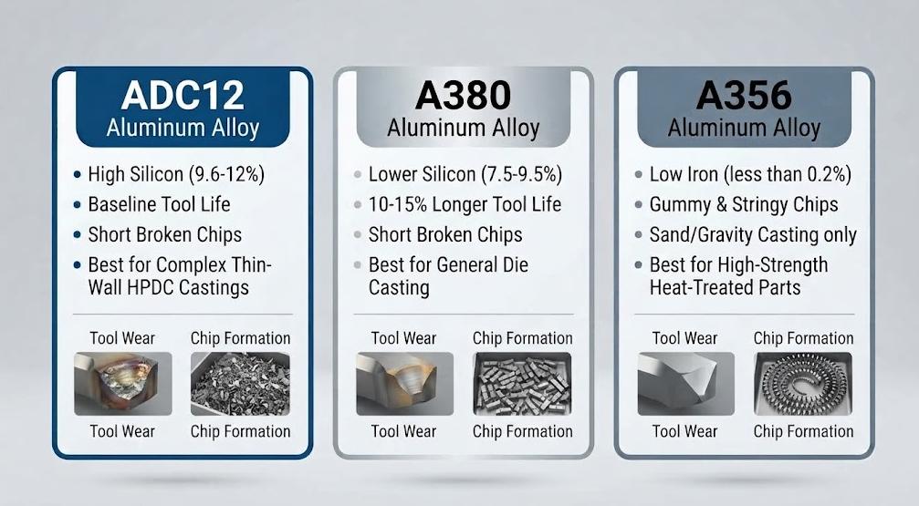
Recommended image: adc12-vs-a380-vs-a356-chip-formation-comparison.jpg — Side-by-side comparison of chip morphology from ADC12, A380, and A356 under identical machining conditions.
Three Alloys, Three Machinability Profiles
The machinability of ADC12 only makes sense when you place it alongside the other common die-cast aluminum alloys. Here’s how they compare:
| Property | ADC12 | A380 | A356 |
| Silicon (%) | 9.6–12.0 | 7.5–9.5 | 6.5–7.5 |
| Iron (%) | ≤1.3 | ≤1.3 | ≤0.2 |
| Copper (%) | 1.5–3.5 | 3.0–4.0 | ≤0.2 |
| Casting Route | High-pressure die casting | High-pressure die casting | Sand, gravity, or low-pressure casting |
| Tool Life (relative) | Baseline | 10–15% longer | Shorter than ADC12 |
| Chip Formation | Short, broken chips | Short, broken chips | Gummy, stringy chips |
| Best For | Complex thin-wall castings | General die casting | High-strength, heat-treated parts |
Data sources: Alloy composition ranges from patent and standard references; casting route guidance from industry comparison; tool life data from JTR comparison.
Three key takeaways:
1. ADC12 vs. A380. A380 has lower silicon (7.5–9.5% vs. 9.6–12.0%) and higher copper (3.0–4.0% vs. 1.5–3.5%). Lower silicon means less abrasive wear — A380 tools genuinely last longer. But A380 requires more careful die-casting parameters and doesn’t flow as well into thin walls. For complex geometries, ADC12’s superior castability often outweighs the tool-life penalty.
2. ADC12 vs. A356. This is where ADC12 shines. A356’s iron content is capped at 0.2% — ten times lower than ADC12. That low iron produces gummy chips, poor chip breakage, and a tendency for built-up edge. ADC12’s iron promotes clean chip formation, reducing the risk of tool chatter and surface defects. A356 also can’t be high-pressure die cast — it’s limited to sand, gravity, or low-pressure routes, which means slower cycle times and higher per-part cost for volume production.
3. The reputation gap. ADC12 is often labeled “difficult” because people compare it to A380 and stop there. But the comparison that matters for most high-volume production is ADC12 vs. A356 — and in that matchup, ADC12’s machinability advantage is real and measurable.
What ADC12 Actually Looks Like on the Shop Floor
Surface Finish and Tool Wear: The Numbers
Under optimized conditions, ADC12 can achieve impressive results:
- Surface roughness as low as 0.25 µm (Ra) with minimum tool wear of 0.001mm using design-of-experiments optimized parameters.
- A high-speed face milling case study achieved Rz = 0.55 µm on ADC12, demonstrating the alloy’s potential for excellent surface finish with the right tooling.
In a real production case study, a timing chain case made from ADC12 was machined with a multi-flute face mill using cutting speeds of 1,571 m/min (roughing) and 1,256 m/min (finishing). The results:
- 1.5× efficiency improvement in roughing, 2.0× in finishing
- Competitor tools began producing burrs at approximately 3,500 pieces
- The optimized solution reached 20,000+ pieces without burr formation — no manual deburring required
That’s not a laboratory result. That’s a production floor number.
The Hard-Spot Problem (And How to Avoid It)
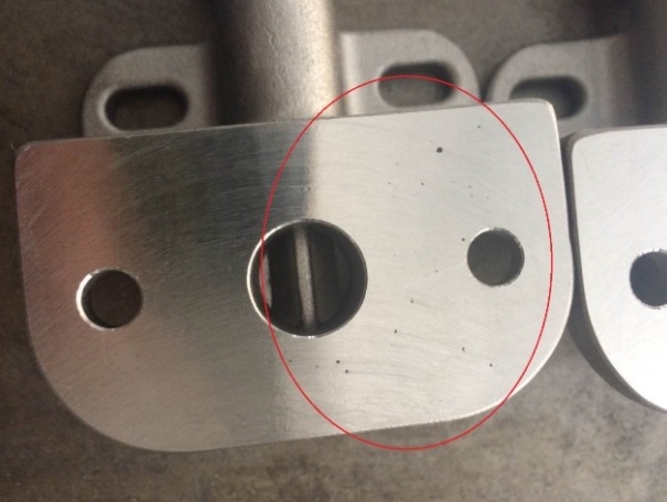
ADC12 does have one genuine weakness that deserves attention: hard spots. When they appear, local hardness can reach 160–180 HV — far above the normal 70–120 HV range for ADC12 castings. These hard spots cause tool breakage, micro-cracks, and premature tool failure.
The root causes are almost always found in the casting process, not the machining process:
- Low nitrogen purity during degassing
- Impure molten aluminum with oxide inclusions
- Insufficient slag removal before pouring
- Undissolved silicon particles or coarse primary silicon
The solution isn’t to machine around the hard spots. It’s to prevent them at the source. Working with a die casting supplier that controls melt quality, nitrogen purity, and slag removal will eliminate most hard-spot risk before the casting ever reaches the CNC station.
This is exactly why JTR integrates die casting services and CNC machining services under one roof. When the same team controls both processes, hard-spot prevention becomes a casting parameter — not an expensive machining problem.
Recommended CNC Parameters for ADC12
Cutting Speed, Feed, and Depth of Cut
| Parameter | Recommendation |
| Cutting speed (carbide) | 200–350 m/min |
| Cutting speed (PCD) | Up to 1,500 m/min |
| Feed rate | 0.10–0.25 mm/rev |
| Depth of cut (finishing) | 0.3–0.5mm (see porosity risk) |
| Tool coating | TiAlN, DLC, or PCD |
| Milling direction | Climb milling preferred |
| Coolant | High-flow, through-spindle preferred |
Tool Selection: PCD vs. Coated Carbide vs. DLC
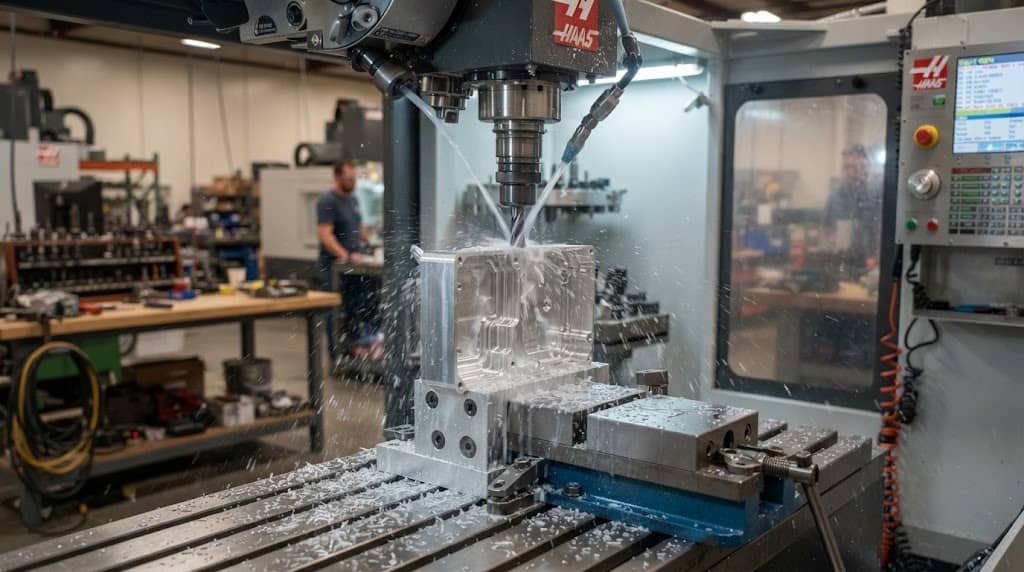
PCD (polycrystalline diamond) tools are the gold standard for high-silicon ADC12. In the timing chain case study, PCD inserts achieved cutting speeds of 1,571 m/min in roughing and 1,256 m/min in finishing — speeds that carbide tools simply cannot sustain on ADC12. PCD is expensive but pays for itself in high-volume production.
TiAlN-coated carbide is the practical middle ground. It handles the abrasive wear from silicon reasonably well and is far more affordable than PCD. Best suited for low-to-medium volume runs or when tool change time isn’t a bottleneck.
DLC (diamond-like carbon) coating specifically addresses the adhesion wear problem — the aluminum sticking to the tool edge. DLC’s low friction coefficient reduces built-up edge and produces “high-quality glossy machined surfaces” on ADC12. This is particularly useful for finishing operations where surface finish is critical.
Surface Finish Targets
| Surface Type | Achievable Ra | Tooling Note |
| General machined surfaces | 0.8–1.6 µm | TiAlN carbide |
| Sealing faces | 0.4–0.8 µm | DLC or PCD finishing |
| Precision bores | 0.25–0.5 µm | PCD with optimized parameters |
How JTR Machines ADC12 Aluminum
From Die Casting to Finished Part: A Single Source
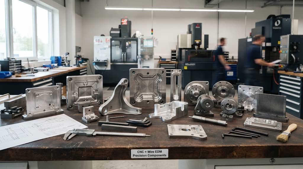
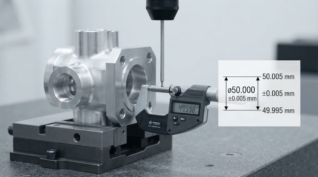
JTR’s ADC12 aluminum CNC machined parts follow a complete process chain: die casting → shot blasting → passivation → CNC milling → CNC drilling → cleaning and packaging. The part shown on our product page measures 499.5 × 358 × 87.1mm — a large housing produced with ±0.018mm tolerance and inspected on a CMM.
The equipment list matters here: 4-Axis Machining Center, vertical machining center, hydraulic press, and CMM. Four-axis capability means complex ADC12 parts can be machined with fewer setups — which directly reduces the risk of tolerance stack-up on multi-face features.
We also produce CNC milling and die casting car parts where the ADC12 casting and CNC finishing are planned as a single production flow.
Why Integrated Casting and Machining Matters for ADC12
When die casting and CNC machining are separated between two suppliers, the casting supplier doesn’t know — or care — about the machining parameters that will be used. The machining supplier receives castings and discovers hard spots, porosity, or dimensional variation only when the tools are already cutting.
JTR’s integrated approach changes the sequence:
- Melt quality control directly targets hard-spot prevention during casting
- First-article test cuts validate chip formation and tool life before full production
- Machining allowance design accounts for ADC12’s specific shrinkage and skin characteristics from the mold design stage
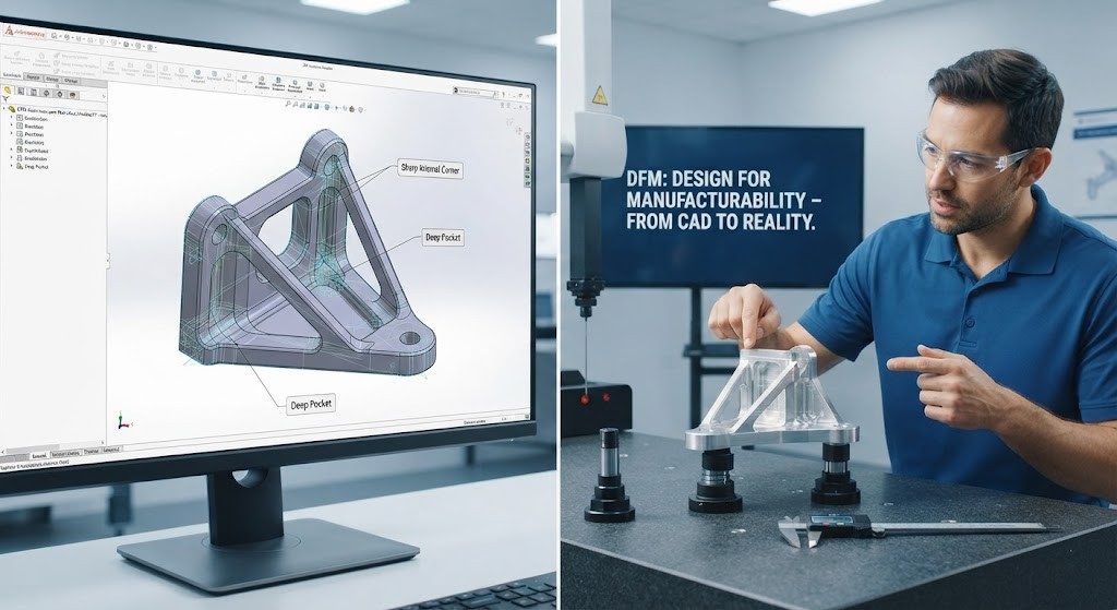
- DFM analysis evaluates tool selection and cutting parameters based on the actual alloy composition, not generic recommendations
For precision casting applications where tighter dimensional control is required, the same integration logic applies — casting parameters and machining parameters are designed together, not sequentially.
Got an ADC12 part that needs precision CNC machining? Upload your CAD file to JTR and we’ll run a DFM analysis that accounts for alloy composition, tool life, and surface finish — before the first chip is cut.
→ Get Your DFM Analysis from JTR