

Why a Part That Passes Every Inspection Can Still Fail in the Field
The hydraulic pressure is holding at 15 bar. Four minutes into the validation cycle, a single bead of oil begins to weep from the wall of the pump housing. No crack. No visible defect. Just a slow, steady leak from what appears to be solid aluminum.
The dimensions were right. The X-ray report showed the casting met ASTM E505 Grade 2 porosity standards. So why was hydraulic fluid weeping through metal?
Here’s what happened: the CNC finishing pass had penetrated the casting’s dense outer layer – the chilled skin – and exposed a network of interconnected porosity hidden inside. A part that passed every dimensional and radiographic check still leaked under real-world pressure.
This isn’t a rare edge case. It’s a systemic problem that costs manufacturers millions in late-stage scrap, and it almost always traces back to one variable that rarely gets enough attention: CNC post processing depth.
If you work with aluminum die castings – whether you’re a machining engineer, a quality manager, or a procurement specialist sourcing from an aluminum die casting manufacturer – understanding this risk will change how you set machining allowances.
The Chilled Skin: Your Part’s Only Defense Against Porosity
What Happens in the First Milliseconds of Die Casting
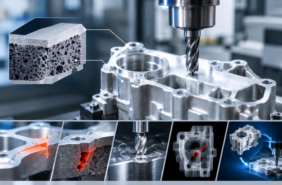
When molten aluminum (such as ADC12 or A380) is injected into a water-cooled steel die at high velocity, the metal in direct contact with the die wall solidifies almost instantly. This rapid thermal quenching creates a highly dense, fine-grained outer layer known as the “chill zone” or “chilled skin.”
The skin is not a coating. It is the same alloy – just solidified under radically different cooling rates. Because of that fast cooling, the skin has virtually zero porosity and higher strength than the metal beneath it.
Beneath this skin, the cooling rate slows dramatically. Entrapped gases and shrinkage voids form in what metallurgists call the dendritic core – a coarser, sponge-like internal structure. The skin is the only thing standing between a pressure-tight housing and a unit that weeps fluid like a sieve.
How Thick Is the Skin? The Numbers You Need to Know
| Source | Skin Thickness | Notes |
| NADCA Structural Design Guidelines | 0.38–0.50mm (0.015–0.020 in.) | Typical for aluminum die castings |
| Published patent data (ADC12, secondary dendrite arm spacing ≤ 5.5 μm) | ≥ 0.5mm | Minimum observed on production parts |
| NADCA P-402 recommended practice | 0.5–0.8mm | Fine-grained, dense layer formed against water-cooled die surface |
Here’s the critical point: these numbers are typical values, not guarantees. The actual skin thickness on any given part depends on die temperature, fill speed, wall thickness, alloy composition, and – perhaps most importantly – process drift. As the die heats up during a high-volume production run, the cooling rate slows, the dendrite arm spacing widens, and the skin gets thinner. A casting that had a robust 0.6mm skin at the start of a shift might have only 0.4mm by hour six.
The skin is not a fixed number. It’s a moving target. And that’s exactly what makes machining depth control so treacherous.
The Critical Depth Threshold: Where Machining Becomes Dangerous
The 0.5mm Line That Most Shops Don’t Know About
Physical analysis of AlSi9Cu3 alloys (the base composition of ADC12) shows that the transition from dense skin to porous core occurs abruptly at depths exceeding 0.5mm – not gradually, but suddenly. Beyond that boundary, the material changes from a reliable pressure barrier to a porous structure that can leak.
Every additional 0.1mm of material removal beyond the safe depth of 0.5mm increases the statistical probability of a leak-test failure by 12% in thin-walled housings.
This is the counterintuitive part that catches even experienced machinists off guard: leaving extra material as a “safety net” for the CNC setup actually increases the risk. The logic seems backwards until you understand the metallurgy – a larger machining allowance sounds safer, but that extra material often requires removing more of the protective skin, exposing the vulnerable core beneath.
The 400% Risk Spike: When 0.5mm Becomes 1.2mm
Quantified production audit data from high-volume runs makes the risk jump clear:
- Machining depth at 0.5mm: Baseline risk. Tool is still within the chilled skin.
- Machining depth at 1.2mm: Probability of exposing a leak path increases by over 400%.
This data comes from auditing high-pressure die casting housing integrity in production environments, and it explains a common and expensive pattern: manufacturers increase machining allowances to ensure clean surfaces, then see leak-test reject rates explode.
A real-world example: one valve body manufacturer suffered a 20% scrap rate during final assembly. The cause was systemic over-machining – an operator was taking a 1.2mm cut from the sealing face to correct a minor flatness deviation, unaware that the safe machining depth was only 0.5mm. By the time those housings reached the hydrostatic test bench, they were essentially sponges.
Practical Depth Ranges: What to Use and When to Validate
Based on multiple sources and production data, here’s the practical guidance for aluminum die casting CNC post processing:
| Surface Type | Recommended Depth | Rationale |
| Critical sealing faces | 0.5–0.7mm (validate by pressure test) | Must stay at or just within the skin boundary; exceeding 0.5mm raises risk sharply |
| Bearing bores / pin holes | 0.3–0.5mm | High precision required; porosity causes fit and function failure |
| Threaded bosses | 0.5–0.8mm | Thread strength depends on dense metal; stripping risk increases beyond this |
| Non-critical mounting surfaces | Up to 1.2mm (if verified) | Can tolerate more removal; must be validated by first-article test |
Important note on sealing faces: The 0.5–0.7mm range for critical sealing faces is sometimes necessary to achieve flatness and surface finish requirements. However, because the risk of exposing porosity rises sharply beyond 0.5mm, any sealing face machined deeper than 0.5mm must be validated through production-realistic pressure testing. Do not assume a clean surface means a pressure-tight part.
The Silent Failure Mode: How Porosity Hides During Machining
Tribothermal Smearing and the False Seal
Here’s a failure mechanism that most machining shops don’t know about – and it’s the reason parts can pass factory inspection and fail in the field months later.
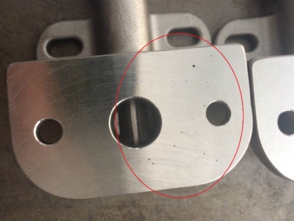
When a CNC tool cuts through aluminum containing micro-porosity, the cutting heat and friction cause the aluminum to undergo plastic flow. Tiny pores get “smeared” over – a false seal forms that looks perfect on the surface. The part passes visual inspection and even short-duration pressure tests.
But this false seal is fragile. Under high-pressure fluid pulses in real-world applications – automotive hydraulic systems, agricultural equipment, industrial pumps – the smeared layer eventually ruptures. The timeline looks something like this:
- 0–100 hours: Surface appears smooth. Pressurized fluid begins navigating the microscopic interconnected pores exposed by the CNC cutter.
- 100–500 hours: The hydraulic pressure overcomes capillary resistance. Sub-surface percolation occurs. The machined face begins to show “sweating” or dark oil dampness.
- 500+ hours: Continuous pressure pulsation (water hammer effect) causes microscopic pores to link and fracture. A macroscopic blowout occurs across the machined face.
The most dangerous porosity is the porosity you can’t see. Tribothermal smearing can mask a leak path during machining, only for it to rupture under real-world pressure cycles.
Why X-Ray Inspection Doesn’t Save You
Many buyers assume that “the X-ray passed, so the casting is fine.” But X-ray inspection evaluates the raw casting – not the final machined part. A casting might be rated ASTM E505 Grade 2 (acceptable porosity levels), but that rating reflects a volumetric average. It doesn’t tell you whether a specific large void sits exactly at the depth where your CNC tool will cut.
A Grade 2 radiograph might show “passing” levels of porosity overall, but if those voids are located exactly at the 0.6mm depth mark, a standard 0.8mm machining cut will open a direct leak path.
Think of it this way: X-ray tells you how much rain is in the cloud. It doesn’t tell you where the lightning will strike.
One documented case: a high-pressure pump housing line had castings that consistently passed X-ray at Grade 1. During final assembly pressure testing at 8 bar, the leakage rate hit 22%. The audit revealed the CNC program was taking a 0.8mm finishing cut on critical sealing faces – completely stripping the 0.5mm chilled skin. By the time the problem was identified, 4,000 units had been produced – all unusable.
How to Set Machining Depth That Actually Works
Step 1 – Map Critical Surfaces Before Tooling
The most effective time to address porosity risk is during mold design – long before the first CNC tool touches metal. Identify every surface that must be pressure-tight, dimensionally precise, or load-bearing:
- Mark all sealing faces, bearing bores, and threaded holes
- Determine maximum allowable machining depth for each critical surface
- Confirm with the die casting supplier that gating and venting design pushes porosity away from critical areas
- Validate actual surface quality at the production machining depth during first-article testing
This maps directly to what NADCA P-402 guidelines recommend: gas and shrinkage defects are naturally pushed toward the thermal center during solidification. Proper gating design keeps those defects away from the surfaces that will be machined.
Step 2 – Use the 70% Rule as Your Starting Point
A simple guideline: machining depth should not exceed 70% of the typical skin thickness. If the typical skin is 0.5mm, that means a maximum cut of approximately 0.35mm. This gives you a safety margin for batch-to-batch variation and process drift.
For critical sealing faces, however, the practical reality is often different. Some production data suggests that sealing faces may need 0.5–0.7mm of material removal to achieve the required flatness and surface finish. In these cases, the machining depth must be validated through production-realistic pressure testing – not just dimensional inspection.
Step 3 – Validate with a Production-Realistic First Article
First-article inspection should go beyond dimensional checks. The validation process should include:
- Machining the sealing face under actual production conditions (real clamping force, real cutting parameters)
- Performing a pressure test on the machined part, not just a dimensional inspection
- If conditions permit, making a sacrificial deep cut on a non-critical surface to reveal the actual distribution of hidden porosity – this is more informative than any X-ray report
- Checking dendrite arm spacing (DAS) as an indicator of cooling rate consistency; wide DAS indicates slower cooling and larger potential for interconnected voids
At JTR, our precision CNC machining services incorporate these validation steps because we’ve seen firsthand what happens when machining depth is treated as an afterthought. We also machine a test cut on non-critical surfaces before committing to critical face depths – a practice we follow on every ADC12 aluminum CNC machined part we produce.
How JTR Controls Depth Before It Becomes a Problem
Die Casting and CNC Under One Roof
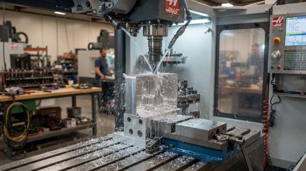
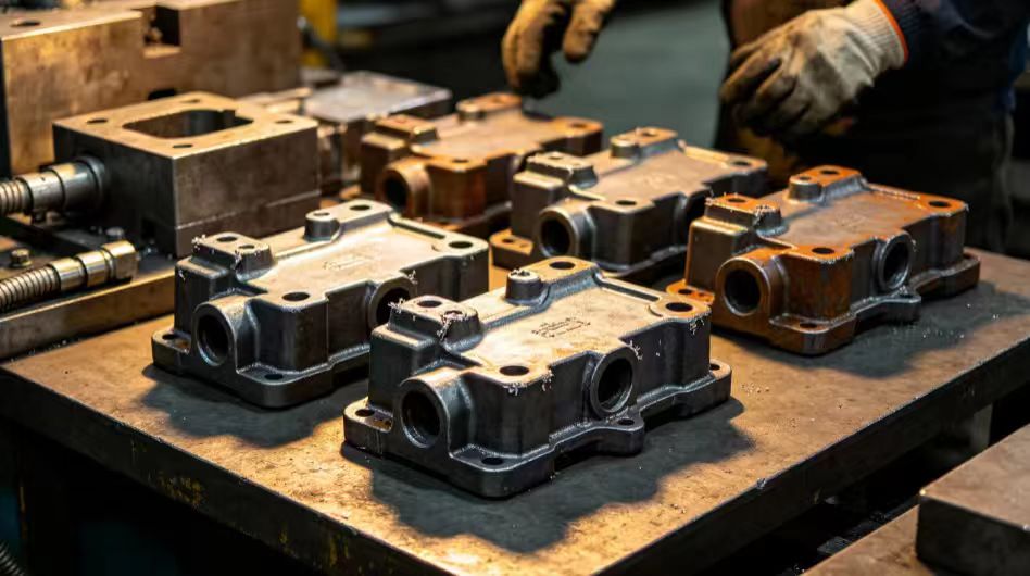
JTR’s core advantage is that die casting services and CNC machining services happen under the same roof. This means machining allowance design doesn’t need to be negotiated between two separate suppliers – we can synchronize skin thickness and critical surface machining depth from the mold design stage itself.
For CNC milling and die casting car parts, this integrated approach has proven especially valuable. Automotive components often have strict pressure-tightness and GD&T requirements, and the window between “enough material to machine clean” and “too much material that exposes porosity” is narrow. Having both processes in one facility means we can adjust casting parameters and machining allowances together, rather than playing catch-up when a problem shows up at the CNC station.
Our precision casting capabilities extend the same philosophy to other casting processes, giving customers a single point of accountability from raw material to finished part.
Inspection That Goes Beyond Dimensional Checks
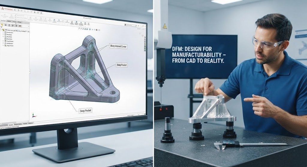
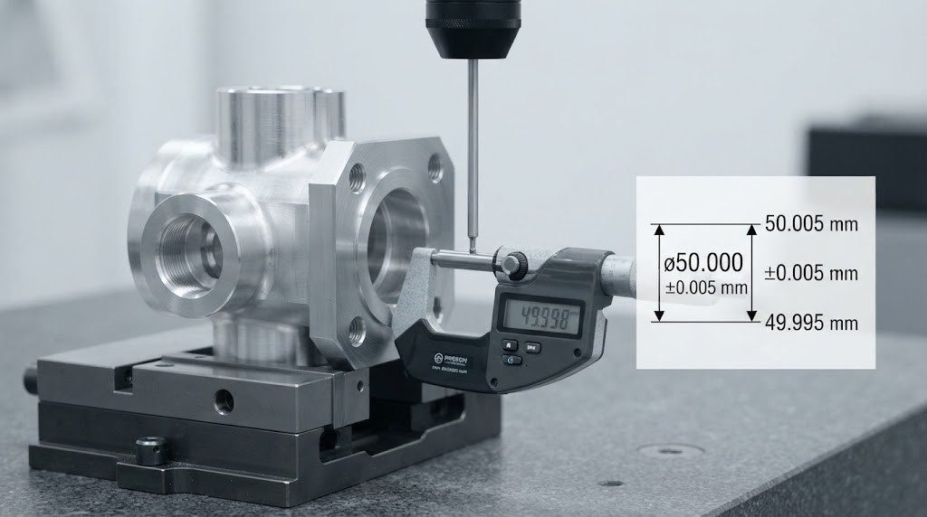
JTR is equipped with CMM (coordinate measuring machines) and other precision inspection tools that verify critical dimensions and geometric tolerances. But more importantly, our DFM analysis evaluates critical surface machining depth against the chilled skin safe zone during the project planning phase – not after the first parts are scrapped.
We recommend that any aluminum die casting manufacturer you work with should be able to answer these questions before production begins:
- What is the expected skin thickness range for this part?
- What is the maximum safe machining depth for each critical surface?
- How will batch-to-batch variation in skin thickness be handled?
- What validation testing will confirm that machined surfaces are pressure-tight?
If a supplier can’t answer these questions, the risk of late-stage leak failures goes up significantly.
Bottom Line
- Aluminum die castings have a dense chilled skin (typically 0.5–0.8mm) that acts as a natural pressure barrier. Beneath it lies a porous dendritic core.
- Safe CNC post processing depth for critical surfaces is 0.3–0.5mm for most applications, with sealing faces occasionally requiring 0.5–0.7mm, but only when validated by pressure testing.
- Beyond 0.5mm, the risk of exposing leak paths rises sharply. Going from 0.5mm to 1.2mm increases leak risk by over 400% in high-volume production.
- Tribothermal smearing can create a false seal during machining – the part looks fine at the factory but fails under real-world pressure cycles months later.
- X-ray inspection is not enough. It evaluates the raw casting, not the final machined geometry. A Grade 2 casting can still fail if the machining depth hits a localized void.
- The most effective control is design-stage coordination between die casting and CNC machining – something JTR provides as a single-source aluminum die casting manufacturer.
Got a die-cast part that needs CNC post processing? Upload your CAD file to JTR and we’ll run a DFM analysis that accounts for skin thickness, machining depth, and porosity risk – before the first tool hits the metal.