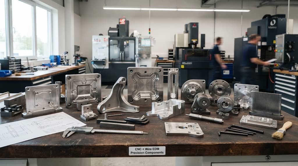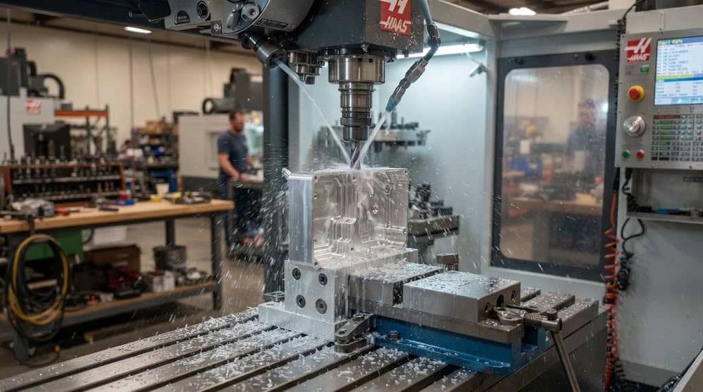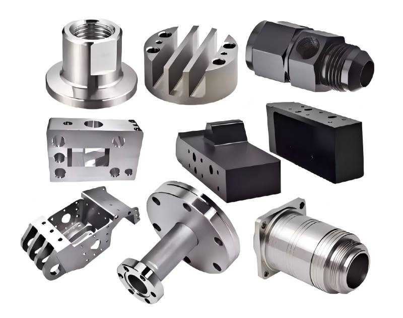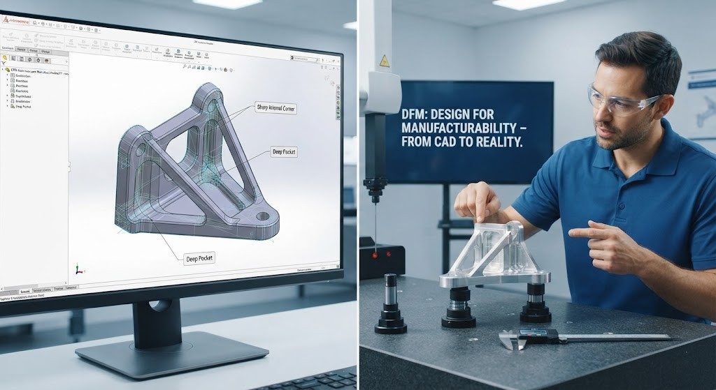


When designing a CNC machined part, the internal corner radius is more than a geometric detail. It affects cutting tool selection, tool access, machining time, tool life, and, ultimately, manufacturing cost.
The reason is straightforward: conventional CNC milling cutters have a circular cutting profile and cannot directly produce a perfectly sharp internal 90-degree corner. When a design requires a very small radius, the manufacturer may need smaller tools, additional finishing passes or a different machining strategy. For cost-effective CNC machining, the goal is not to eliminate small radii. It is to specify the largest practical radius that meets the part’s functional requirements. This principle is part of a broader set of CNC machining DFM guidelines covering tool accessibility, pocket geometry, tolerances and manufacturing setup.
What Is an Internal Corner Radius in CNC Machining?
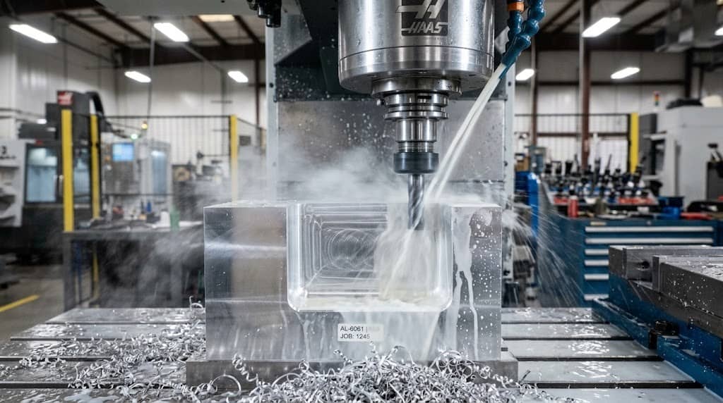
A CNC machining internal corner radius is the rounded transition where two internal surfaces meet, such as the corner of a milled pocket, slot or cavity.
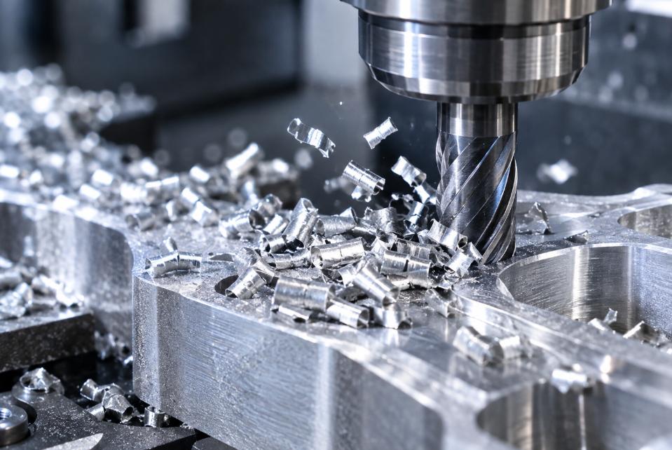
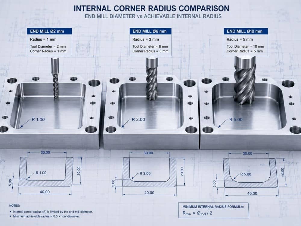
In CNC milling, the achievable radius is closely related to the cutting tool geometry. For example, a conventional 6 mm diameter end mill has an approximately 3 mm cutting radius. When the tool moves around an internal pocket, its circular profile leaves a corresponding radius at the corner. Therefore, the smaller the required internal corner radius, the smaller the cutting tool may need to be.
This relationship is important when designing pockets, cavities and other milled features because tool diameter also affects cutting stability, machining time and tool life.
Why Can’t CNC Milling Easily Produce Sharp Internal Corners?
1. Cutting Tool Geometry
A standard end mill has a round cutting profile. It cannot occupy the zero-radius intersection of two perpendicular internal walls. For example, if a pocket requires a 1 mm internal radius, an end mill with a larger cutting radius cannot completely machine that corner. A smaller tool or an alternative process may be required. When a geometry requires a feature that conventional milling cannot economically produce, alternative processes such as Wire EDM service may need to be evaluated.
2. Tool Access
The problem becomes more significant when a small radius is combined with a deep or narrow pocket. The tool must have sufficient access while maintaining adequate rigidity. A long tool extension can increase deflection and vibration, while a small-diameter tool may require more conservative cutting parameters.
For this reason, internal corner radius should always be evaluated together with:
- Tool diameter
- Tool length and overhang
- Pocket depth
- Material
- Required tolerance
- Machine configuration
3. Tool Rigidity
Smaller tools generally have lower bending stiffness than larger tools. When machining deep cavities or difficult materials, this can increase sensitivity to deflection, vibration and tool breakage. A smaller tool may therefore solve a geometric problem while creating a machining problem.
How Does Internal Corner Radius Affect CNC Machining Cost?
A small internal radius does not automatically make a part expensive. Its cost impact depends on the complete geometry, material, quantity and required tolerances. However, unnecessarily small radii can introduce several additional manufacturing requirements.
1. Smaller Cutting Tools
A tight internal radius may require a smaller end mill that cannot be used for the majority of the material-removal operation. The manufacturer may therefore need separate roughing and finishing tools.
2. Longer Machining Time
Small tools generally require more conservative cutting conditions, particularly when tool deflection or breakage must be controlled.
A simplified relationship is: Smaller radius → smaller tool → lower practical cutting rate → potentially longer cycle time
This is one reason why unnecessarily small internal corners can increase part cost.
3. Additional Tool Changes
A complex pocket may require: Roughing tool → semi-finishing tool → small-radius finishing tool
Additional tool changes increase machining time and can add programming and process-planning requirements.
4. Higher Tool Wear or Breakage Risk
Small-diameter tools are more sensitive to:
- Excessive cutting loads
- Tool deflection
- Vibration
- Long tool overhang
- Difficult-to-machine materials
These factors can increase tool consumption and process risk.
5. Additional Inspection Requirements
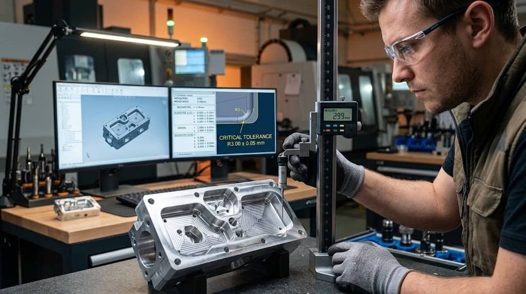
If the radius itself has a tight dimensional tolerance, additional measurement and process control may be required. Engineers should therefore define CNC machining tolerances according to the functional requirements rather than specifying unnecessarily tight values. The manufacturing cost is therefore affected not only by cutting the radius, but also by verifying that the finished feature meets the engineering specification.
What Determines the Minimum CNC Internal Corner Radius?
There is no single minimum internal corner radius that applies to every CNC machined part. The practical radius depends on several factors:
| Factor | Effect on CNC Internal Radius |
| Tool diameter | Limits the smallest radius that can be directly machined |
| Pocket depth | May require longer or smaller tools |
| Material | Influences cutting conditions and tool selection |
| Part geometry | Determines tool accessibility |
| Tolerance | Can increase finishing and inspection requirements |
| Machine configuration | Affects tool approach and accessibility |
Therefore, a radius that is practical for a shallow aluminum pocket may not be equally practical for a deep stainless-steel cavity. The minimum practical CNC internal corner radius depends on tool diameter, pocket depth, material, machine capability and required tolerance. This is more useful as a DFM principle than applying a fixed minimum radius to every part.
Recommended Internal Corner Radius for CNC Machining
For general CNC milling, designers should use a radius that is compatible with standard cutting tools whenever the part’s function allows it.
| Design Condition | Recommended DFM Approach |
| General internal corners | Use a radius compatible with standard end mills |
| Deep pockets | Increase the radius where practical |
| Very small radius | Confirm tool diameter and tool access |
| Hard materials | Avoid unnecessarily small radii |
| Tight radius tolerance | Review finishing and inspection requirements |
| Cost-sensitive parts | Favor standard tooling |
A larger radius can often improve manufacturability without changing the functional performance of the component. The key principle is to use the largest functional radius rather than the smallest geometrically possible radius.
How to Design Internal Corners for Lower CNC Machining Cost
1. Use the Largest Functional Radius
If an internal corner does not perform a specific mechanical function, there is usually little benefit in making its radius as small as possible. A larger radius can allow the use of a larger and more rigid cutting tool.
2. Match the Radius to Standard Tooling
Designing features around commonly available end mills can reduce the need for specialized tooling. This should be considered during CAD and DFM review rather than after the design has already been released for production.
3. Avoid Unnecessary Sharp Corners
A 0 mm internal radius should generally be reserved for situations where the geometry or assembly actually requires it. For many pockets and cavities, a radiused corner provides the same functional result with fewer machining constraints.
4. Use Different Radii Strategically
Not every internal corner on a component needs the same radius. A functional mating feature may require a smaller radius, while non-functional corners can use larger radii. This allows the design to balance function, manufacturability, and cost
5. Consider Dog-Bone Reliefs for Square Mating Parts
A dog-bone relief can be useful when a square or rectangular component must fit into a CNC-machined pocket. Because a milling cutter leaves a radius at the internal corner, the rounded corner can interfere with the mating part. A small localized relief creates additional clearance without requiring the entire pocket to be machined with an extremely small-radius tool.
This can be an effective DFM solution for:
- Square inserts
- Rectangular components
- Press-fit features
- Mechanical mating pockets
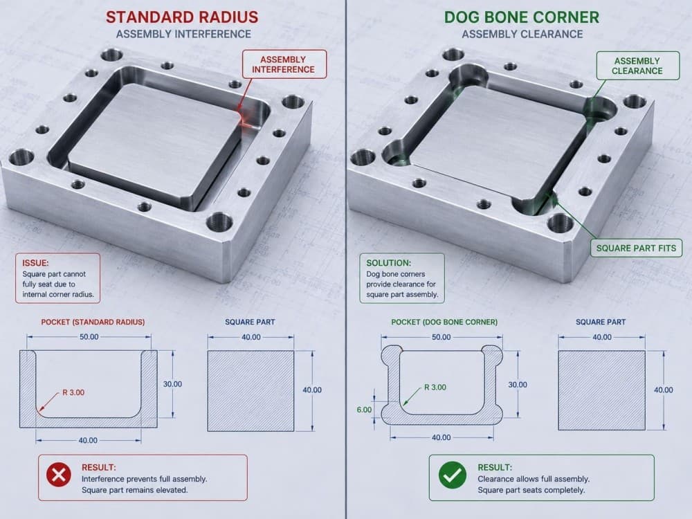
Sharp vs. Radiused Internal Corners: CNC Cost Trade-Off
| Design Approach | Machining Consideration | Potential Cost Impact | Typical Application |
| Sharp internal corner | Difficult with conventional milling | Higher | Specific functional requirements |
| Very small radius | May require small tooling | Higher | Restricted geometry |
| Moderate radius | More compatible with standard tools | Lower | General CNC parts |
| Large radius | Better tool access and rigidity | Lower | Non-functional corners |
| Dog-bone relief | Adds localized clearance | Can reduce machining difficulty | Square mating components |
These are DFM tendencies rather than fixed pricing rules. Actual cost depends on material, part geometry, production quantity, tolerance, machine configuration and the complete manufacturing process.
When Should a Small Internal Radius Be Used?
Small internal radii should not automatically be removed from a design. They can be appropriate when required for:
1. Mating Components: A specific radius may be necessary to achieve the required clearance, positioning or fit.
2. Sealing or Functional Surfaces: Certain components may require controlled geometry because of their operating or assembly requirements.
3. Flow Channels: Internal passageways may require particular corner geometry based on the application’s functional requirements.
4. Clearance Requirements: A smaller radius may sometimes be necessary to preserve limited space within a component.
The DFM principle is therefore not making every radius large. It is to use small radii where they provide functional value, and avoid unnecessarily small radii where they do not.
CNC Internal Corner Radius: From CAD Design to Manufacturing
Internal corner radius should be reviewed as part of the complete CNC manufacturing process.
- CAD Geometry: Internal radius + pocket depth + tool access
- Tool Selection: Diameter + length + rigidity + material compatibility
- Machining Strategy: Roughing + semi-finishing + finishing
- Inspection: Dimensional and geometric verification
This approach helps identify potential manufacturing constraints before production begins. For complex components, 5-axis CNC machining can provide additional tool access and allow difficult surfaces to be approached from different orientations. However, the appropriate machining process still depends on the actual geometry, material, tolerance and production requirements. However, the appropriate machining process still depends on the actual geometry, material, tolerance and production requirements.
FAQ
Q1: What is the recommended internal corner radius for CNC machining?
There is no universal minimum. The practical radius depends on tool diameter, pocket depth, material, machine capability and required tolerance.
Q2: Can CNC machining produce a sharp 90-degree internal corner?
Conventional CNC milling generally cannot produce a perfectly sharp internal corner because standard milling cutters have a finite radius. Another machining strategy or process may be required when a sharp corner is functionally necessary.
Q3: Does a smaller internal corner radius increase CNC machining cost?
It can. A smaller radius may require smaller tools, slower cutting conditions, additional passes, more tool changes or tighter process control.
Q4: What happens if a CNC pocket radius is smaller than the cutting tool?
The tool cannot fully reach the specified geometry. The manufacturer may need a smaller tool, modified geometry, another machining strategy or a different manufacturing process.
Q5: What is a dog-bone relief in CNC machining?
A dog-bone relief is a small additional circular cut at an internal corner that provides clearance for a square or rectangular mating component.
Q6: How can I reduce CNC machining costs related to internal corners?
Use the largest radius that satisfies the functional requirement, design around standard tooling where possible, avoid unnecessary sharp corners and review tool access during DFM.