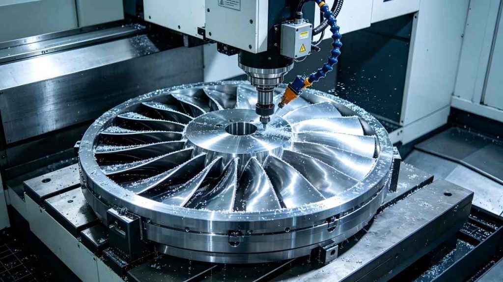
The blisk (bladed disk) is a key part of gas turbines and aircraft engines. It is one of the hardest parts to create in high-end precision manufacturing because of its complicated shape and the need for very high accuracy. Traditional machining processes don’t always work, which leads to high rejection rates, tool wear, and delays in production.
This is where 5-axis turn-mill compound machining comes in. By combining 5-axis simultaneous machining with turn-mill capabilities, manufacturers can now overcome the most stubborn blisk machining challenges—from thin-wall deformation and material hardness to interference risks and cumulative clamping errors.
This post will discuss the main problems with making precision blisks, show how 5-axis CNC machining for blisks overcomes them, and give a real-life example from JTR Machine. This book will help you learn how to make blisks in large quantities with great precision and efficiency, no matter if you are an aerospace engineer or a production manager.
What is a Blisk & Its Importance in Aerospace Industry
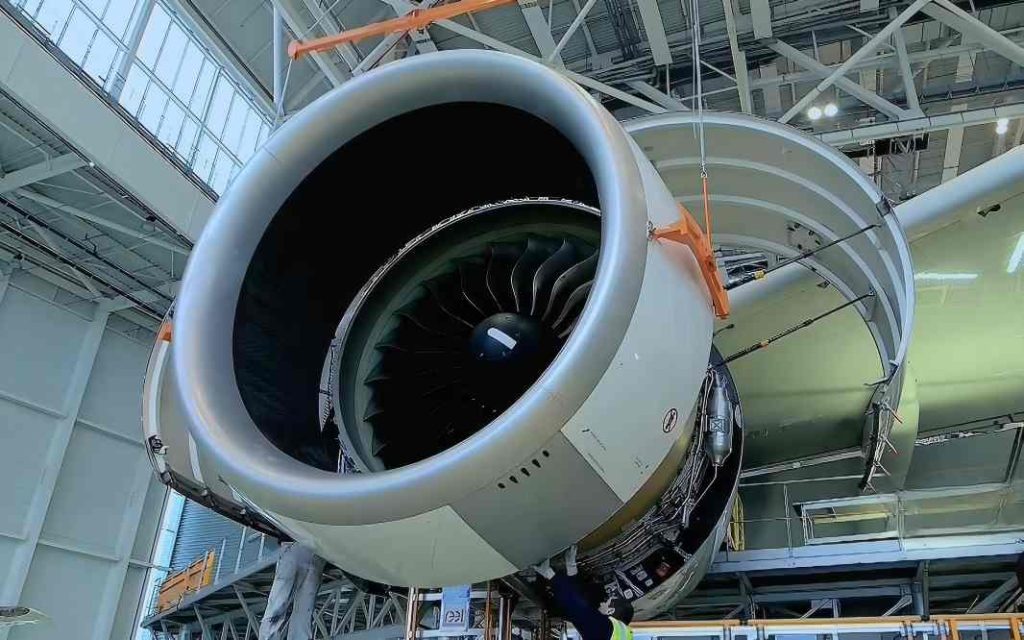
A blisk (bladed disk) integrates turbine blades and the disk into a single component, eliminating traditional connection structures like dovetails or bolts. The design, through its aerodynamic efficiency, weight reduction, and mechanical failure risk decrease, has become essential for contemporary aviation operations.
Blisk aerospace applications include:
- Civil and military aircraft engines
- Helicopter engines
- Gas turbines for power generation
Blisk machining has become a bottleneck in aerospace manufacturing since it is hard to do and requires advanced machining technologies to get beyond. As engine performance needs rise, the need for precise blisk parts keeps growing.
But the same things that make blisks useful—twisted blades, tight channels, and thin walls—also make them very hard to machine with regular tools.
Key Challenges in Blisk Machining
Before exploring solutions, it is essential to understand the four major pain points in bladed disk manufacturing: structure, material, precision, and process inefficiency.
1. Poor Openness & High Interference Risk
A blisk has narrow channels between twisted blades, and the tool is prone to collision and interference during machining. This puts high requirements on tool path planning and machine tool RTCP function. Without proper 5-axis capability, tool holders will collide with blade surfaces, causing scrap or damage.
Blisk machining interference is one of the most common reasons for CNC program rejection. Blisk narrow channel machining demands advanced simulation and collision avoidance strategies.
2. Thin-Wall Deformation
Blade wall thickness is typically only 0.5–2mm, which is easy to produce tool deflection, chatter, and deformation rebound under cutting force. This makes it difficult to control finishing size and profile tolerance.
Blisk thin-wall deformation is especially severe when machining titanium alloys or nickel-based superalloys, where cutting forces are high. Blisk machining chatter not only affects surface quality but also accelerates tool wear.
3. Difficult-to-Cut Materials
Nickel-based superalloys and titanium alloy (TC4, Ti6Al4V) are two common materials used to make blisks. These materials are very strong, very thick, and don’t transmit heat well, which makes cutting temperatures high, tools wear out quickly, and tools stick or burn easily.
Titanium alloy blisk machining requires specialized cutting parameters and tool coatings. Similarly, superalloy blisk cutting demands excellent thermal management. Blisk tool wear is a major cost driver in traditional processes.
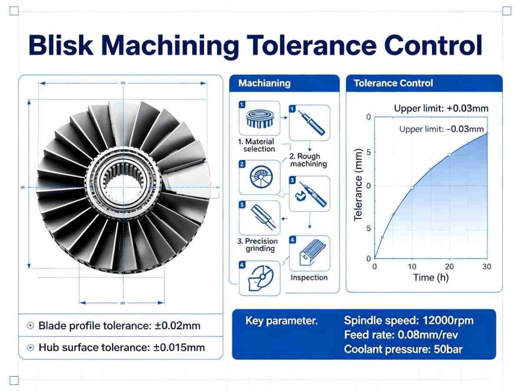
4. Ultra-High Precision Requirements
Blade profile tolerance is usually ±0.003mm or higher. The blade root fillet, leading/trailing edge, and flow channel surface require continuous smoothness without tool marks or steps.
Achieving blisk profile tolerance at this level is impossible with 3-axis machines or multiple setups. Blisk surface roughness (typically Ra≤0.8μm) demands high dynamic stability and precision control. High-precision blisk machining is a true test of machine capability.
5. Cumulative Errors from Multiple Clamping
Traditional processing requires five or more clampings: turning blank → milling blade → drilling → grinding → polishing. Each clamping introduces positioning errors, making it difficult to ensure final geometric tolerance.
Blisk multiple clamping errors accumulate quickly. Even with precision fixtures, blisk machining tolerance control becomes unreliable when parts are moved between machines.
6. Other Key Difficulties
- Tool vibration and chatter caused by long-neck tools in deep cavity machining
- Difficulty in corner cleaning and transition area processing
- Large thermal deformation during long-term processing
These challenges explain why traditional methods cannot meet modern aerospace demands. The industry needs a fundamental change—and that change is 5-axis turn-mill compound machining.
How 5-Axis Turn-Mill Compound Machining Solves Blisk Machining Challenges
5-axis turn-mill compound machining integrates 5-axis simultaneous machining and turn-mill compound technology. It is currently the most advanced solution for blisk machining, perfectly solving the above pain points with its unique technical advantages.
1. One-Time Clamping, Eliminate Cumulative Errors
By integrating turning, milling, drilling, and other processes into one machine, all processing procedures are completed with one clamping. This avoids positioning errors caused by multiple clampings and ensures part accuracy consistency.
5-axis turn-mill one-time clamping is a game changer. It directly addresses blisk machining error elimination by removing the root cause: repeated setups.
2. 5-Axis Linkage, Solve Interference & Complex Structure Problems
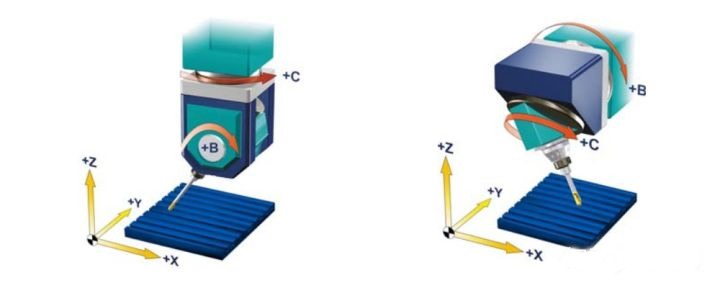
With A/B dual rotation axes and RTCP (tool tip following) function, the tool can be tilted and rotated freely, easily accessing narrow channels between blades. This avoids tool interference and enables precise machining of complex curved surfaces.
5-axis linkage machining allows the tool to approach from optimal angles. Blisk interference avoidance becomes automatic with proper CAM programming. The 5-axis RTCP function ensures that tool tip position remains accurate regardless of machine kinematics.
3. Precision Control, Meet Ultra-High Tolerance Requirements
Equipped with full-closed loop grating rulers and AI thermal compensation systems, modern 5-axis turn-mill centers can real-time compensate for thermal deformation and tool wear. This ensures that profile tolerance and surface roughness meet blisk requirements (Ra≤0.8μm, profile tolerance ±0.003mm).
5-axis precision machining combined with blisk thermal compensation allows stable production even in non-temperature-controlled shops. AI-driven blisk machining further improves consistency by predicting and adjusting for thermal drift.
4. Optimize Cutting Process, Reduce Tool Wear & Deformation
For difficult-to-cut materials, cutting parameters and tool path trajectories are optimized. Dry or micro-lubrication technology reduces cutting temperature and tool wear. At the same time, lower cutting forces help avoid thin-wall deformation.
Blisk cutting parameter optimization is built into the CAM workflow. 5-axis tool path planning ensures smooth engagement and exit. Titanium alloy cutting technology has advanced significantly, making high-speed machining of blisks practical.
5. Improve Efficiency, Reduce Production Cost
Compared to traditional processes, the processing cycle is shortened by 60% or more. Fewer processes, lower tool consumption, and reduced labor costs enable batch and efficient production of blisks.
Blisk machining efficiency directly translates to lower cost per part. 5-axis turn-mill cost reduction comes from fewer machines, less handling, and higher first-pass yield. Blisk mass production becomes economically viable.
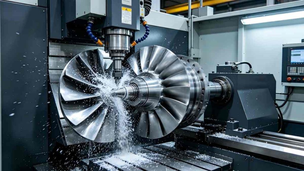
Case Study: JTR Machine 5-Axis Turn-Mill Compound Machining for Aerospace Blisk
The theoretical advantages of 5-axis turn-mill technology are best understood through a real-world application. The following case study demonstrates JTR Machine 5-axis turn-mill machining in action.
Project Background
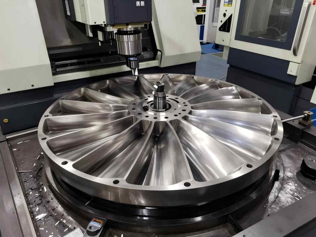
A domestic aerospace engine manufacturer required the mass production of titanium alloy blisks (diameter Φ320 mm, 12 complex blades). Their core requirements were stringent: blisk profile tolerance ≤ ±0.003 mm, surface roughness Ra ≤ 0.6 μm, and the integration of multiple processes (turning, milling, drilling) for batch delivery of 120 pieces per year. The client’s traditional 3-axis plus turning process required five separate clampings, leading to low efficiency, large cumulative errors, and an inability to meet delivery targets.
JTR Machine 5-Axis Turn-Mill Compound Machining Solution
To meet this challenge, JTR Machine deployed its advanced 5-axis turn-mill compound machining center, equipped with A/B dual rotation axes, full-closed loop grating rulers, and an AI thermal compensation system. A hydraulic fixture was used for one-time clamping with inner hole positioning to ensure a uniform reference.
The JTR blisk solution process flow was:
- Rough machining: Turning of outer circle and end face, followed by rough milling of the blade channels using high-performance carbide tools.
- Finishing: 5-axis linkage milling of the complete blade profile, including root fillet corner cleaning using specialized lollipop cutters.
- Auxiliary processing: C-axis indexing to mill radial cooling holes and other secondary features.
Crucially, JTR Machine aerospace machining experts optimized tool paths and cutting parameters specifically for titanium alloy, applying trochoidal roughing and constant chip-load finishing strategies to avoid chatter and overcut. The entire process was proven for 24-hour continuous, unattended processing.
Project Results
The outcomes were measured and verified:
- Accuracy: Achieved blade profile tolerance of ±0.0025 mm, surface roughness Ra ≤ 0.6 μm, and hole position tolerance ±0.003 mm. All metrics were better than client requirements.
- Efficiency: The total processing cycle was reduced from 72 hours per piece (using the old method) to just 22 hours per piece on the JTR 5-axis turn-mill. This represents a 5-axis efficiency improvement of 227%.
- Cost & Quality: Single-piece processing cost was reduced by 35%. The batch qualification rate reached an impressive 99.5%, successfully supporting the client’s annual delivery target. These JTR blisk machining results demonstrate the tangible ROI of the technology.
Client Feedback
“JTR’s 5-axis turn-mill compound machining perfectly solved our blisk machining pain points, ensuring both precision and efficiency, and becoming our reliable long-term cooperative partner.” — Aerospace Engine Manufacturer Client
Why Choose JTR Machine for 5-Axis Turn-Mill Blisk Machining
Choosing the right manufacturing partner is as critical as choosing the right technology. JTR Machine stands out as a leader in JTR 5-axis machining service for several compelling reasons.
1. Professional Technical Strength
JTR Machine operates more than 70 precision CNC processing equipment units, including a fleet of advanced 5-axis turn-mill compound machining centers. Backed by a team with decades of experience in JTR precision manufacturing, we possess the institutional knowledge to handle the most complex blisk geometries.
2. Strict Quality Control
Quality is built into every step of the process, not only thought about after. JTR meets the quality requirements set by ISO9001:2008, TS16949, and IATF. We use high-precision Hexagon CMMs, optical projectors, and surface roughness testers in our inspection lab to make sure that every JTR blisk machining partner gets components that meet or exceed print standards.
3. Customized Solution Capability
No two blisks are identical. JTR Machine offers one-on-one customized service, tailoring 5-axis turn-mill processing solutions based on the client’s specific material, precision, and batch requirements.
4. Efficient Delivery & 24/7 Service
In aerospace, speed to market matters. JTR Machine provides fast quotation within hours and delivers parts in days. Our 24/7 consulting service ensures that any client questions or processing problems are solved immediately, minimizing downtime.
FAQs
Q1: What materials of blisks can JTR Machine process with 5-axis turn-mill compound technology?
A: JTR Machine specializes in difficult-to-cut aerospace materials, including titanium alloy (TC4, Ti6Al4V), nickel-based superalloys (Inconel 718, Waspaloy), stainless steel, and aluminum alloys. JTR blisk material processing covers the full range.
Q2: How long does it take to process a single blisk with 5-axis turn-mill compound machining?
A: It depends on size and complexity. For the Φ320 mm titanium alloy blisk in the case study, cycle time was 22 hours/piece—60% faster than traditional processes. Contact JTR Machine with your CAD file for a specific JTR Machine blisk processing cycle estimate.
Q3: Can JTR meet the ultra-high precision requirements of aerospace blisks?
A: Absolutely. JTR Machine’s 5-axis turn-mill centers are equipped with full-closed loop grating rulers and AI thermal compensation, stably achieving profile tolerance ±0.003 mm and surface roughness Ra ≤ 0.8 μm, meeting all standard aerospace specifications.
Q4: What is the batch qualification rate of JTR Machine‘s blisk machining?
A: JTR Machine consistently achieves a batch qualification rate of 99.5% or higher for blisk production. This JTR Machine blisk qualification rate is a direct result of rigorous process control and in-process inspection.