In the precision manufacturing industry, achieving superior surface finish and dimensional accuracy in 5-axis simultaneous milling is a critical objective for CNC machining service factory engineers. While many programmers focus heavily on step-over distances and feed rates, the underlying G-code structure—specifically the selection of G17, G18, and G19 — plays a decisive role in how the CNC control system processes motion. Improper plane management often leads to micro-vibrations, visible chatter marks, and inconsistent tool paths. This technical guide examines how to optimize plane selection to achieve smoother motion in complex multi-axis environments.
The Technical Role of G17, G18, and G19 in Multi-Axis Situations
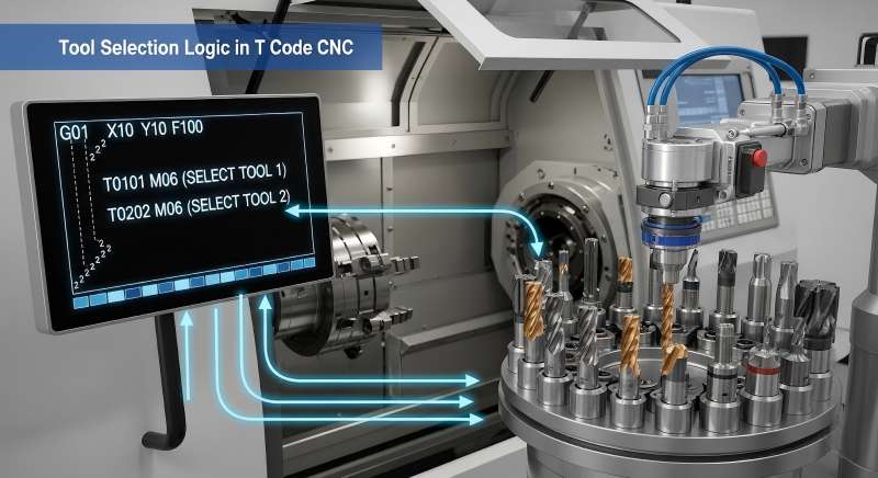
In traditional 3-axis milling, selecting planes is very simple, with G17 used for the XY plane, G18 for the ZX plane, and G19 for the YZ plane. These commands tell the control which axes are being used for the arc commands (G02/G03), as well as the direction for tool radius compensation (G41/G42).
But in 5-axis simultaneous milling, the tool axis vector changes all the time with respect to the workpiece. Most CAM programs have default settings where they generate thousands of small G01 straight-line pieces to represent one curve. While this defines the geometry, it forces the controller to accelerate and decelerate at every single point. By correctly utilizing G17, G18, and G19, engineers can enable the controller to recognize local arcs within a 3D space, switching from “point-to-point” motion to “smooth arc” motion. This transition significantly reduces the computational load on the CNC’s Look-ahead buffer and results in a more fluid movement of the machine’s rotary axes (A, B, or C).
Strategies for Plane Optimization and Motion Smoothing
1. Enabling Arc Filtering and Post-Processor Optimization
The most effective way to improve CNC surface finish optimization is through arc filtering within the CAM software. When a post-processor is configured to support plane switching, it analyzes the tool path and identifies segments that can be fitted into an arc.
- Linear vs. Circular Interpolation: A path described by 100 G01 lines will never be as smooth as a single G02 or G03 arc command. By defining the correct plane (e.g., G19 for a vertical radius on a cylinder), the controller uses its internal algorithms to maintain a constant velocity.
- Vector Consistency: In 5-axis motion, the plane is not just a static 2D coordinate. Modern controllers can handle “tilted working planes.” Ensuring the post-processor aligns the G17-G19 command with the local coordinate system (LCS) of the feature being machined is essential for high-speed accuracy.
2. Synergizing with RTCP (Rotation Tool Center Point)
When executing 5-axis simultaneous motion, RTCP (known as G43.4 in Fanuc or M128 in Heidenhain) is active. RTCP allows the programmer to define the path based on the tool tip rather than the machine pivot point.
Optimizing planes under RTCP requires the controller to synchronize linear axes (X, Y, Z) and rotary axes (A, B, C) perfectly. If the plane selection is mismatched with the tool’s primary oscillation direction, the controller may struggle to apply tool radius compensation. This leads to “stuttering” where the rotary axes make micro-adjustments to compensate for the lack of a smooth arc definition, resulting in surface vibration marks. Engineers should ensure that the plane selection remains consistent with the primary curvature of the part surface to minimize these adjustments.
3. Leveraging Advanced Contour Control and Pre-processing
Modern CNC systems like the Fanuc 31i series or Siemens 840D include high-level features such as AICC II (Artificial Intelligence Contour Control) or Top Surface. These functions look ahead at hundreds of blocks of code to predict changes in direction.
- Buffer Management: Frequent and unnecessary switching between G17, G18, and G19 can sometimes cause a “break” in the look-ahead buffer, as the controller must reset its interpolation logic.
- The “Global G17” Approach: For extremely complex surfaces where the curvature changes constantly (like an aero-engine blade), many engineers prefer to stay in G17 and rely on the controller’s Nano-interpolation and Spline interpolation capabilities. This prevents the “hesitation” that can occur during plane switching.

System-Specific Implementation and Best Practices
Fanuc Systems: High-Speed Processing
For Fanuc-based 5-axis simultaneous milling, engineers should focus on the interaction between plane selection and the G05.1 Q1 (AI Nano Workpiece Interpolation) command. Under this setting, the sensitivity of the controller is high when considering the smoothness of the data fed into it. If the CAM output defines the circular arcs using G17/G18/G19, the AICC program can more easily find Acc/Dec curves.
Siemens Systems: CYCLE832 and Compressor Functions
In Siemens controllers, the CYCLE832 (High Speed Settings) command works in tandem with “Compressor” functions (COMPCAD or COMPSURF). These functions take the G17-G19 defined paths and “smooth” them into a continuous spline. Correct plane definition helps the compressor identify which points belong to a specific geometric feature, preventing the “rounding” of sharp corners while maintaining high feed rates.
Heidenhain: PLANE Spatial and M128
Heidenhain systems excel at handling spatial geometry. Using the PLANE SPATIAL command allows the engineer to define a working plane in 3D space. When combined with M128, the controller manages the G17, G18, and G19 plane selection internally. The focus here shifts to the TCPM (Tool Center Point Management) settings, where the “smoothness” parameter can be adjusted to prioritize either speed or contour accuracy.
Case Study: Impeller Machining and Surface Quality
In a recent aerospace component manufacturing project involving a titanium impeller, our engineering team compared two programming methods. The first method used standard G01 linear segments with a fixed G17 plane. The second method utilized an optimized post-processor that triggered G18/G19 plane selection for the leading-edge radii of the blades.
Results:
- Surface Finish: The optimized plane approach reduced the average roughness (Ra) from 1.6μm to 0.8μm.
- Processing Time: The machine maintained a more consistent feed rate, reducing the total cycle time by 12%.
- Data Volume: The G-code file size was reduced by 40% due to the use of circular interpolation commands (G02/G03) instead of thousands of G01 lines.
The Engineer’s Checklist for Plane Optimization
To achieve the best results in a CNC machining service factory, engineers should follow this technical checklist:
- Post-processor check: Verify that your post-processor is able to generate G17, G18, and G19 code according to the local geometry in the toolpath.
- Arc fitting tolerance: Set the CAM filtering arc tolerance just tighter than your tolerance requirements.
- Controller parameters: Verify that controller parameters for AICC II, Top surface, or CYCLE832 are set correctly to recognize circular interpolation in the current plane.
- Consistency: Avoid switching planes within a single continuous cut unless the tool vector shifts significantly.
Being proficient at the shift from G17 to G18 and G19 allows the CNC programmer to go past just learning to program and tap into the power of 5-axis simultaneous milling machines. That’s where the difference lies between high-end machining services in industries such as aerospace, medical, and mold making.
FAQ
Q1: Why is it necessary to choose G17 / G18 / G19 planes in 5-axis simultaneous milling even when using RTCP?
A1: While it is true that RTCP, such as Fanuc G43.4 and Heidenhain M128, are applied, plane selection defines whether the CNC controller will interpret the circular interpolations (G02/G03) and radius compensations (G41/G42) correctly. If the planes are properly selected, then the CNC controller will apply arc fitting techniques rather than processing thousands of minute linear commands (G01).
Q2: Should I always use arc filtering to switch between G17, G18, and G19 planes in my post-processor?
A2: It depends on the geometry. For parts with distinct local radii—such as impeller blades or mold cavities—enabling arc filtering to switch planes is highly effective. However, for extremely organic, high-point-density surfaces (like turbine blades), frequent plane switching can sometimes interrupt the controller’s pre-processing flow. In those specific cases, maintaining a Global G17 while using advanced features like Fanuc Top Surface or Siemens COMPSURF is often the better strategy to maintain high feed rates.
Q3: How does improper plane selection cause chatter marks on a 5-axis finished part?
A3: Improper selection often forces the CNC system to approximate curves using high-frequency G01 linear blocks. The rapid acceleration and deceleration of the machine at each point under high feed rates can cause vibrations called “micro-vibrations.” Additionally, if there is an improper relationship between the plane of the tool and its orientation, then the rotational axes (A, B, or C) will make inconsistent micro-movements to maintain their programmed positions. All this causes a chattering pattern known as faceting.