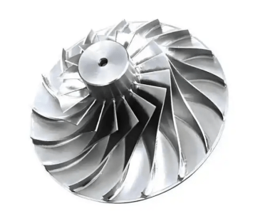
The growing significance of sectors like aerospace, commercial space, and eVTOL— electric aerial commuter vehicles — has altered the dynamics of industrial engineering. Engineers often find themselves engaged in the fabrication of thin-walled components having high aspect ratios, e.g., in many cases, such elements are processed from aluminum 6061-T651 and 7075 alloy. With the slimmest unequivocal wall thickness of less than 1.0 mm and depths beyond 100mm, traditional 3-axis machining processes have struggled significantly with dimensional control. The precision machining for aerospace applications has a superior test in that it has to produce items with a total tolerance of 0.01mm, while ensuring that the inherent wavy shape is controlled. The present communication discusses the physical mechanisms of deformation and suggests a solution to the problem of accurate deformation machining.
Mechanical Analysis of Deformation in Aluminum Alloys
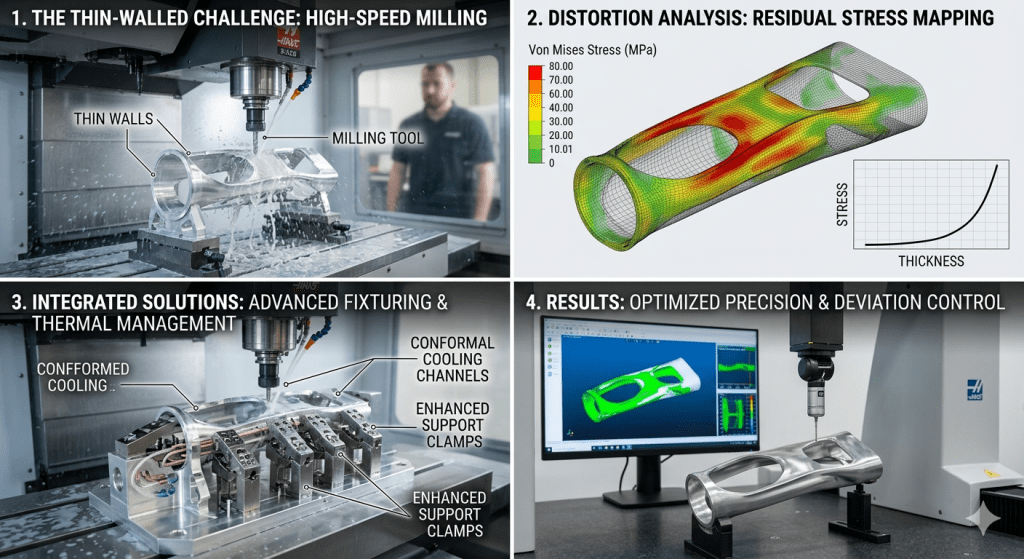
Deformation in aluminum thin-wall components is primarily driven by three factors: the release of residual internal stresses, mechanical cutting forces, and thermal expansion.
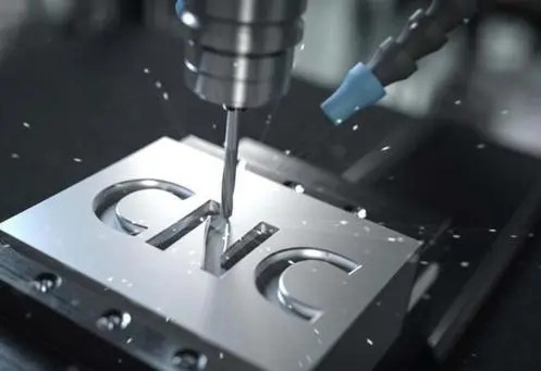
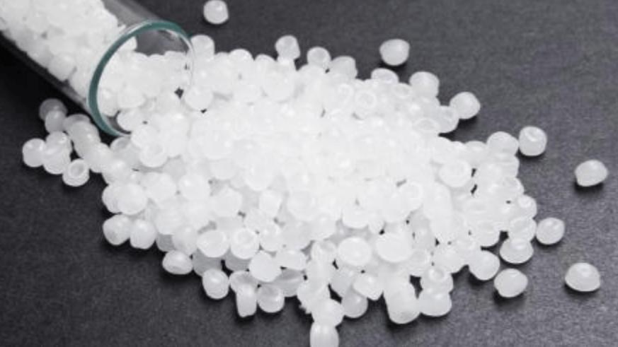
Aluminum plate stock is produced through rolling, quenching, and stretching. These processes induce residual stresses within the crystalline structure of the material. When a large volume of metal is removed during the CNC process, the equilibrium of these internal stresses is disrupted. The material undergoes spontaneous deformation to reach a new state of equilibrium, resulting in warping or twisting.
Cutting forces are also a significant problem. High aspect ratio machining involves materials that have very poor stiffness. The deflection produced in the process due to cutting forces may be greater than the allowable tolerance range. In addition, thin walls are prone to regenerative chatter, which is a type of self-exciting vibration that is produced due to the interplay between the tool and workpiece. Chatter produces surface irregularity on the workpiece as well as deflection in its direction, thus producing an undersized wall thickness.
Thermal issues add to inaccuracies in the process. Aluminum has a high thermal expansion rate. The thermal effect due to high-speed milling at the shear point causes the expansion of the material. If the temperature produced is not adequately removed, then the dimension obtained during the machining when the part is hot will reduce when it cools back to room temperature.
Technical Comparison: Standard vs. Advanced Methodologies
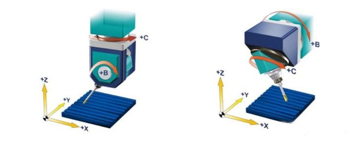
The way to overcome these difficulties is to switch from conventional 3-axis machining to systematic and comprehensive CNC manufacturing technologies with high accuracy. The table below compares conventional solutions with the requirements of the 2026 technical standards in industrial manufacturing.
| Technical Parameter | Standard 3-Axis Process | High-Precision 5-Axis Process (2026 Standard) |
| Workpiece Setup | Conventional Vise/Clamping | Zero-point Clamping & Vacuum Fixturing |
| Machining Strategy | Sequential Side Milling | Simultaneous Symmetric Milling |
| Material Stress Mgmt | None (Raw Stock) | Cryogenic Stabilization / Multi-stage Aging |
| Cutting Speed (Vc) | 180 m/min | 350 m/min (High-Dynamic Siemens 840D SL) |
| Feed Rate (Fz) | 0.05 mm/tooth | 0.12 mm/tooth (AI-Optimized Loading) |
| Tooling Interface | ER Standard Collets | Hydraulic Damping / Thermal Shrink Fit |
| Dimensional Deviation | 0.15 – 0.30 mm | < 0.008 mm |
| Surface Finish (Ra) | 1.6 – 3.2 μm | < 0.4 μm (Direct-to-Finish) |
Core Technology Paths for High Aspect Ratio Machining
Achieving sub-0.01mm precision requires the integration of optimized cutting strategies, advanced tooling, and intelligent machine control.
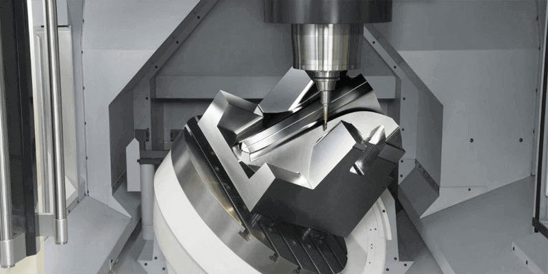
1. Simultaneous Symmetric Milling
Conventional machining involves cutting one side of a wall completely before proceeding to the other. This method concentrates stress on one side of the thin wall, leading to immediate deformation. Symmetric milling involves the simultaneous or alternating removal of material from both sides of the wall. By balancing the cutting forces, the net vector of force acting on the wall is significantly reduced. This approach maintains the structural integrity of the part throughout the machining cycle, preventing the “spring-back” effect associated with non-balanced material removal.
2. Damping Technology and Tooling Geometry
The selection of cutting tools is critical for suppressing chatter in Aluminum 6061 thin-wall CNC production. Standard end mills often have uniform helical flutes, which generate consistent harmonic frequencies that amplify vibration in thin walls.
The industry standard for 2026 emphasizes the use of variable helix and variable pitch end mills. These tools disrupt the periodic frequency of the cut, preventing the buildup of regenerative chatter. Furthermore, it is imperative that rigid hydraulic dampers are used on the machining tools. This is because such machines have built-in dampers that act as shock absorbers of the micro vibrations, thus making it possible to achieve a greater depth of cut ratio without any negative impact on surface finish.
3. AI-Driven Predictive Compensation
The current generation of CNC machines, which can incorporate FANUC or Siemens control systems, uses intelligent servo technology based on AI algorithms to improve accuracy in terms of dimensions. For high-precision machining of aerospace components, thermal compensation is required. Sensors incorporated into the machine detect temperatures within the spindle and the machine base. Thermal expansion of all machine components is computed by the control system, which constantly modifies the tool offset. Thus, the tool will always remain in the same place relative to the part, independent of the thermal environment.
Implementation Checklist for Process Optimization
To achieve accurate and consistent results in the machining of complex thin-walled parts, the following procedures are suggested:
- Material Pre-treatment: The material needs to be subjected to cryogenic treatment at around -196 degrees centigrade. It aids in stabilizing the structure of aluminum and redistributing internal stress within the material.
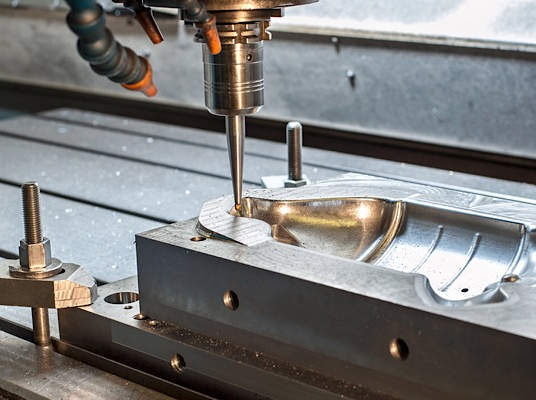
- Strategic Roughing: Perform rough milling with high speed but shallow depth. This will be done to remove most of the material without compromising the structure. A minimum allowance of 0.3mm to 0.5mm must still be left during finishing.
- Stress Relief Cycles: For critical aerospace components, perform a stress relief annealing cycle between roughing and finishing. This allows the material to reach a stable state before final tolerances are applied.
- Finish Machining Environment: Execute the final finishing passes in a temperature-controlled environment (±1°C). The use of Minimum Quantity Lubrication (MQL) is recommended over flood coolant to provide consistent lubrication without the thermal shock associated with high-pressure fluid impacts on thin walls.
- Inline Inspection: Utilize high-precision touch probes on the machine tool to measure the part features immediately after the final cut. This allows for automated correction of tool offsets if deviations are detected before the part is unclamped.
Controlling deformation in high aspect ratio thin-walled parts requires a transition from reactive machining to proactive process management. By combining symmetric cutting force strategies with advanced hardware such as damped tool holders and utilizing the real-time feedback loops of modern CNC controllers, it is possible to achieve sub-0.01mm tolerances.