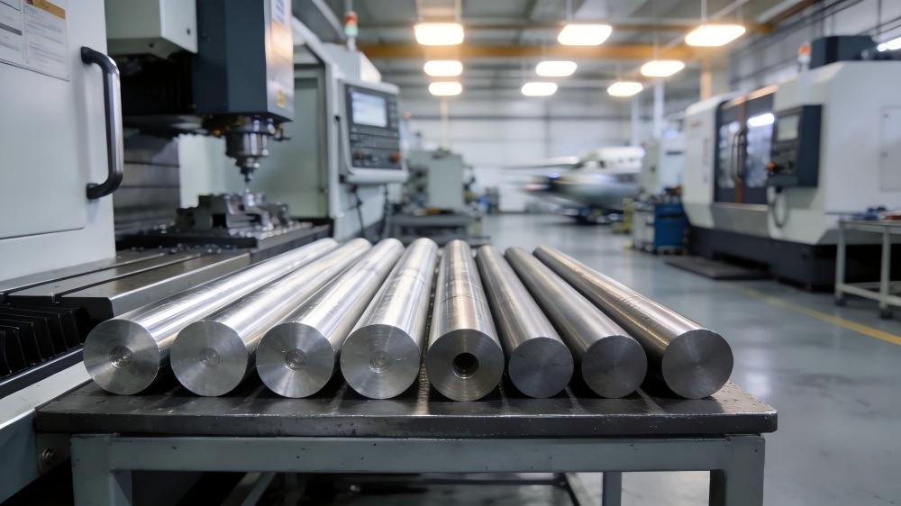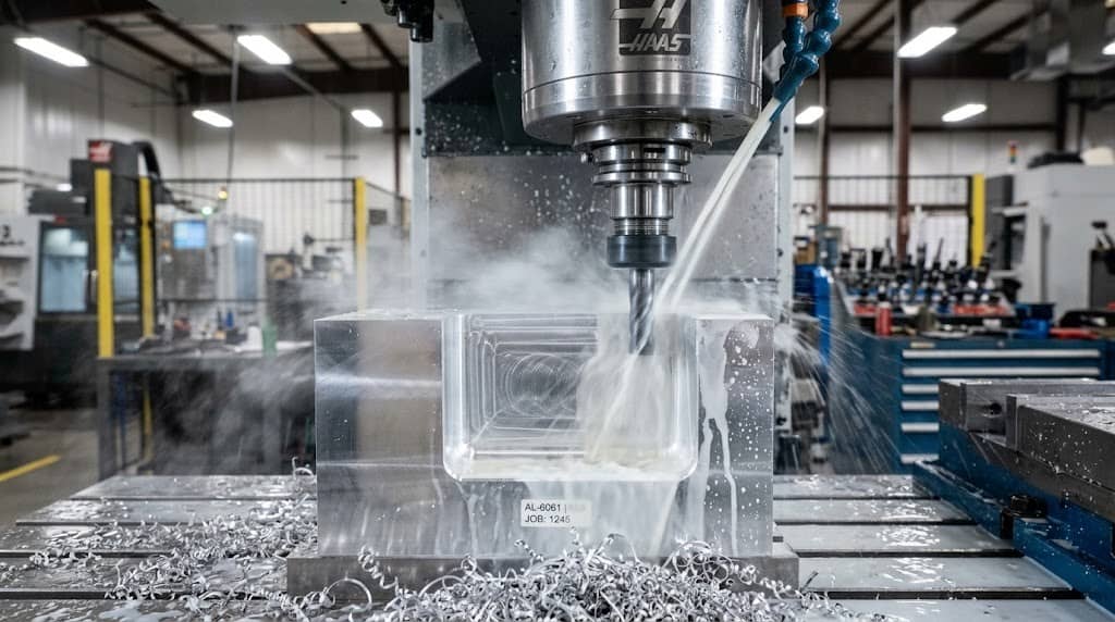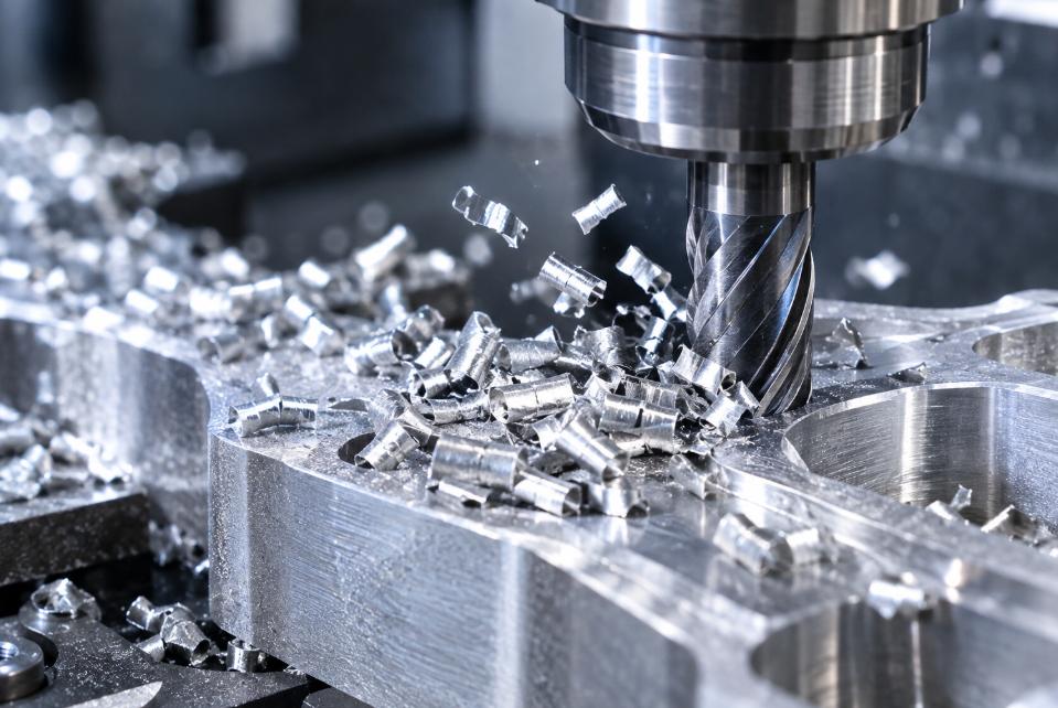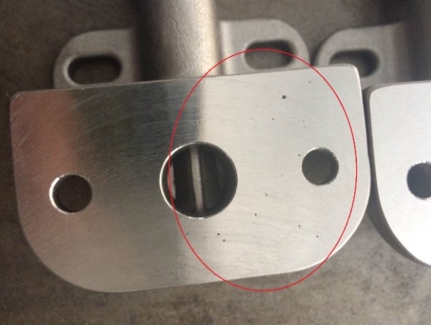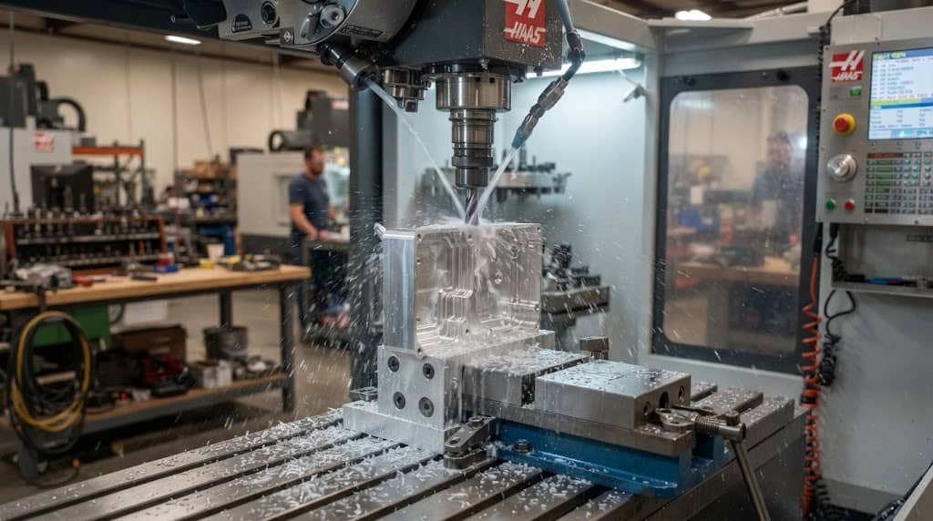


Designing a CNC machined part is more than creating a precise 3D model. A part can be fully functional in CAD and still be difficult, slow, or expensive to manufacture. Features such as sharp internal corners, excessively thin walls, deep pockets, unnecessarily tight tolerances, complex undercuts, and difficult-to-access surfaces can significantly increase machining time and production cost.
CNC machining Design for Manufacturability (DFM) addresses these issues before production begins. By considering cutting tools, machine access, workholding, material behavior, tolerances, surface finish, and inspection requirements during the design stage, engineers can create parts that are easier to machine, more consistent in quality, and more economical to produce.
This guide explains the most important CNC machining design guidelines for engineers, product designers, and procurement teams, from wall thickness and hole design to tolerances, threads, surface finishes, material selection, and 3-axis vs 5-axis machining.
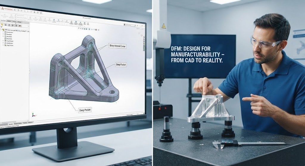
What Is DFM in CNC Machining?
Design for Manufacturability (DFM) is the process of designing a component so that it can be manufactured efficiently, reliably, and economically while still meeting its functional requirements. For CNC machining, DFM means considering the physical limitations of the manufacturing process while the part is still being designed.
A CNC machine may be capable of producing highly complex geometries, but that does not mean every geometry is equally practical to manufacture. The actual result depends on factors such as:
- Cutting tool diameter and length
- Tool access and orientation
- Machine rigidity
- Workholding method
- Material hardness and machinability
- Cutting forces and tool deflection
- Required tolerances
- Surface finish requirements
- Number of machining setups
- Inspection requirements
The goal of DFM is therefore not simply to make a part easier to manufacture by removing features. Instead, the goal is to achieve the required function using geometry and specifications that are compatible with efficient machining.
Why Should DFM Start at the CAD Stage?
Manufacturing problems are much cheaper to solve before machining begins. For example, changing a sharp internal corner to a suitable radius may require only a minor CAD modification. If the same problem is discovered after CNC programming, fixture preparation, or machining, it may result in programming changes, additional tooling, rework, material waste, or schedule delays.
A typical production sequence looks like this:
CAD design → DFM review → quotation → CAM programming → workholding → CNC machining → finishing → inspection
The earlier manufacturing considerations are introduced, the more opportunities there are to reduce unnecessary cost and risk.
The Most Important CNC Machining Design Guidelines at a Glance
The following principles provide a practical starting point for most CNC-machined metal and plastic parts.
| Design Feature | Recommended Approach | Manufacturing Benefit |
| Internal corners | Use practical radii instead of sharp 90° corners | Allows more efficient cutting tools |
| Wall thickness | Avoid unnecessarily thin walls | Reduces vibration and deformation |
| Pocket depth | Avoid extremely deep and narrow cavities | Reduces tool deflection |
| Hole diameter | Use standard sizes when possible | Avoids unnecessary special tooling |
| Hole depth | Keep deep holes to a practical minimum | Improves chip evacuation |
| Threads | Prefer standard thread sizes | Simplifies tooling and inspection |
| Tolerances | Apply tight tolerances only where required | Reduces machining and inspection cost |
| Undercuts | Avoid unnecessary undercuts | Simplifies tool access |
| Setups | Design for fewer machining orientations | Reduces setup time and alignment risk |
| Surface finish | Specify only functionally necessary finishes | Avoids unnecessary secondary processing |
These are general DFM principles rather than universal manufacturing limits. Actual capabilities depend on the material, geometry, machine configuration, tooling, workholding method, and required production volume.
Design Practical Wall Thickness for CNC Machining
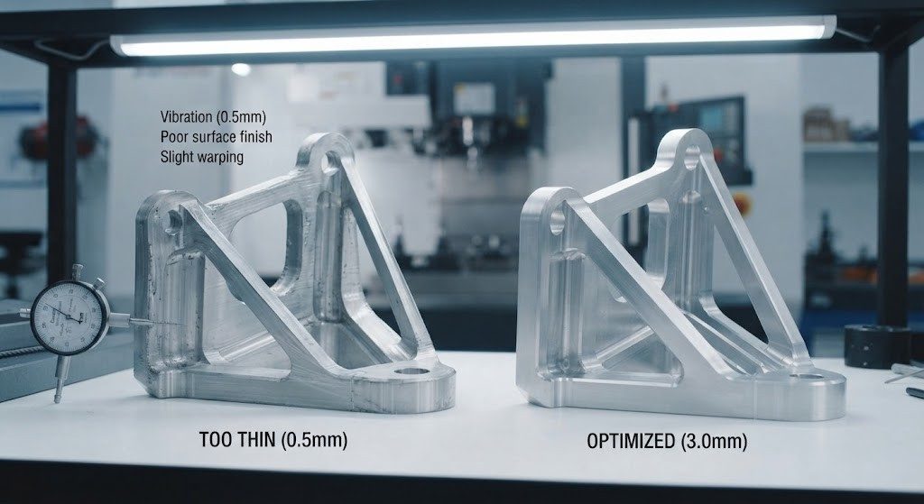
Wall thickness is one of the most important factors affecting CNC machining stability. A thin wall can deflect under cutting forces, vibrate during machining, or deform because of heat and residual stress. These problems become more significant when the wall is tall relative to its thickness.
Why Are Thin Walls Difficult to Machine?
When a cutting tool contacts a thin section, the cutting force can cause the material to move instead of allowing the tool to remove material cleanly. Potential consequences include:
- Dimensional variation
- Vibration and chatter
- Poor surface finish
- Wall deformation
- Tool marks
- Difficulty maintaining tight tolerances
For many metal CNC applications, approximately 1.0–1.5 mm can be considered a practical starting point for thin walls, but this should never be treated as a universal minimum. A 1 mm wall that is 5 mm high behaves very differently from a 1 mm wall that is 50 mm high.
How to Improve Thin-Wall Designs
If a thin wall is functionally necessary, consider:
- Increasing wall thickness where possible
- Reducing unsupported wall height
- Adding ribs for structural support
- Machining the feature with a suitable tool orientation
- Using multiple roughing and finishing passes
- Choosing a more suitable material or machining strategy
The wall height-to-thickness ratio is often more important than thickness alone.
Use Appropriate Internal Corner Radii
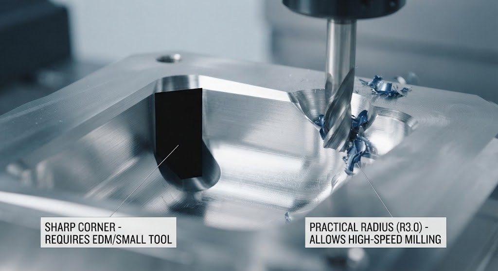
One of the fundamental limitations of CNC milling is the inability of a conventional round cutting tool to create a perfectly sharp internal corner. An end mill has a circular cutting profile. As a result, a nominal 90-degree internal corner will naturally contain a radius.
Why Sharp Internal Corners Increase Cost
A very small internal radius requires a smaller cutting tool. Smaller tools generally have:
- Lower rigidity
- Lower allowable cutting forces
- Higher risk of deflection
- Greater sensitivity to vibration
- Longer machining time
- Potentially shorter tool life
Therefore, unnecessarily small corner radii can make a part more expensive without providing additional functional value.
A Better Approach
Whenever the application permits, use the largest practical internal radius. For example, replacing a tiny corner radius with a larger radius can allow the manufacturer to use a larger and more rigid cutter.
A practical DFM principle is:
Do not design a smaller internal radius than the function actually requires.
For deep pockets, the relationship between radius and pocket depth becomes particularly important. A larger radius can often make deep-pocket machining significantly more stable.
Avoid Extremely Deep and Narrow CNC Pockets
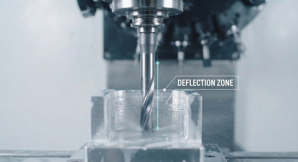
Deep cavities are common in housings, brackets, manifolds, fixtures, and structural components, but they can create significant machining challenges. As pocket depth increases, the required cutting tool often becomes longer relative to its diameter. A long tool is less rigid and more susceptible to deflection and vibration.
Problems Associated With Deep Pockets
Deep and narrow pockets can result in:
- Tool deflection
- Chatter
- Poor dimensional accuracy
- Poor surface finish
- Difficult chip evacuation
- Reduced material removal rates
- Increased machining time
For conventional milling, a depth-to-width ratio around 3:1 to 4:1 can be used as a general design starting point, but the actual limit depends on tool diameter, material, machine rigidity, and geometry.
How to Improve Deep-Pocket Designs
If possible:
- Increase pocket width
- Reduce pocket depth
- Increase the internal corner radius
- Use stepped geometry
- Change the machining orientation
- Consider 4-axis or 5-axis machining
- Divide the component into multiple parts when practical
The objective is to create sufficient access for a rigid cutting tool rather than forcing a long, flexible tool into a narrow cavity.
Follow Practical CNC Hole Design Guidelines
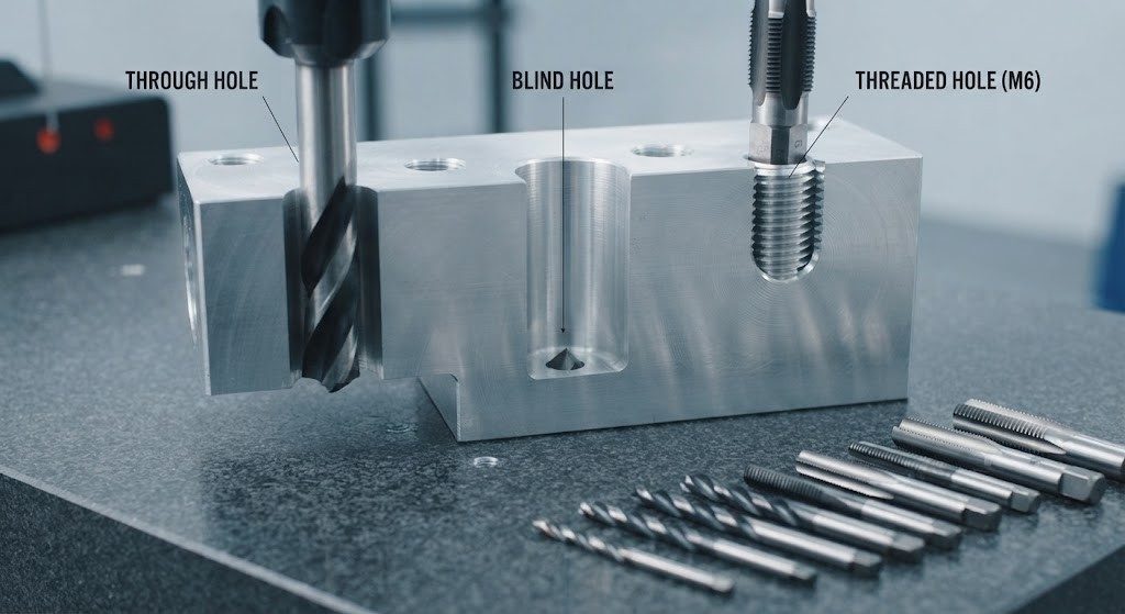
Holes are among the most common features in CNC-machined parts, but their size, depth, tolerance, and location can have a major effect on manufacturability.
Use Standard Hole Sizes Whenever Possible
Standard drill sizes are usually more economical because they are widely available and do not require special tooling. If a design requires a non-standard diameter, the manufacturer may need:
- A special drill
- Reaming
- Boring
- Interpolation
- Additional inspection
Therefore, if a standard diameter meets the functional requirement, it is generally preferable.
Consider Hole Depth Carefully
Deep holes are more difficult than shallow holes because of:
- Drill deflection
- Chip evacuation
- Heat generation
- Tool wear
- Hole straightness
For many conventional drilling operations, a hole depth of approximately 4× the hole diameter can serve as a useful initial reference, but actual capability varies considerably with material, drill type, coolant strategy, and machine setup.
Blind Holes vs. Through Holes
Through holes are generally easier to drill and inspect because chips can exit through the opposite side. Blind holes require additional consideration for:
- Drill tip clearance
- Chip evacuation
- Thread depth
- Hole-bottom geometry
- Depth control
If a blind hole is required, specify the functional depth, rather than simply making the hole deeper than necessary.
Design Threads Around Standard Sizes
Threaded holes are frequently required for fasteners, covers, assemblies, and mounting features. Whenever possible, use commonly available thread standards and sizes such as:
- M3
- M4
- M5
- M6
- M8
- M10
- 1/4-20
- 10-32
Using standard threads simplifies machining, tooling, gauging, and replacement.
Do Not Overdesign Thread Engagement
More thread depth does not automatically mean a stronger connection. For many applications, approximately 1.5× to 2× the nominal diameter can serve as a starting point for thread engagement, particularly in suitable materials. The actual requirement should be determined by material strength, fastener size, joint loading, and engineering requirements. For example, an M6 thread does not necessarily need a very deep threaded section simply because additional depth is available.
For blind tapped holes, remember that:
Thread depth is not the same as total hole depth.
The drill tip and tapping clearance need to be considered when designing the hole.
Avoid Unnecessary Undercuts
Undercuts are features that cannot be reached by a standard cutting tool from a conventional machining direction. They may be required for functional reasons, but unnecessary undercuts can increase manufacturing complexity.
Why Are Undercuts Difficult?
A standard 3-axis CNC milling machine primarily moves the cutting tool relative to the workpiece along three linear axes. If a feature is hidden behind another surface, the cutting tool may not be able to physically reach it.
Manufacturing options may then include:
- Special undercut cutters
- Additional setups
- 4-axis machining
- 5-axis machining
- Wire EDM
- Alternative component designs
DFM Recommendation
Before adding an undercut, ask:
Does this feature provide a necessary functional benefit? If the answer is no, redesigning the geometry may substantially reduce manufacturing cost.
If the undercut is functionally essential, communicate it clearly in the engineering drawing and discuss the required process with the CNC manufacturer.
Design for Tool Accessibility
A CNC machine can only manufacture a feature if the cutting tool can reach it with sufficient clearance. This is why tool accessibility should be considered directly in the CAD design process. Engineers should evaluate:
- Tool approach direction
- Tool diameter
- Tool length
- Spindle clearance
- Adjacent walls
- Pocket depth
- Part orientation
A geometry may be technically machinable but still require an expensive setup or specialized tool.
A Simple DFM Question
For every critical feature, ask:
Can a standard cutting tool reach this surface at a practical angle? If the answer is uncertain, the design should be reviewed before production.
Minimize the Number of CNC Setups
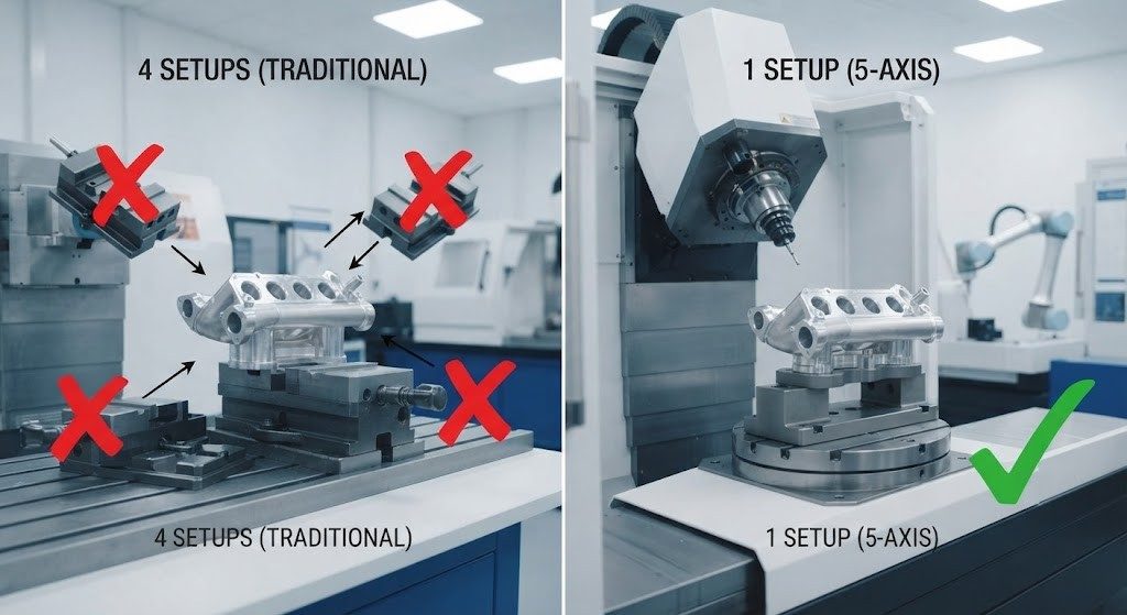
Every additional setup can increase production time and alignment requirements. For example, a part requiring one setup may be substantially more economical than a similar part requiring four separate orientations.
Additional setups can increase:
- Setup labor
- Fixture requirements
- Alignment time
- Handling
- Accumulated positioning error
- Inspection requirements
Design Features Around a Stable Datum
Where possible, create accessible reference surfaces that can be used for:
- Workholding
- Part alignment
- Inspection
- Datum establishment
A well-designed part should make it straightforward for the manufacturer to locate and securely hold the workpiece.
Do Not Over-Specify CNC Machining Tolerances
Tight tolerances are often necessary for functional interfaces, but applying them to every dimension can significantly increase cost. For example, a bearing bore may require tight dimensional and geometric control, while an external non-functional surface may not.
Standard vs. Tight Tolerances
Tight tolerances may require:
- Additional finishing passes
- More stable cutting conditions
- Specialized tooling
- Temperature control
- More frequent measurement
- CMM inspection
- Higher rejection risk
Therefore: Specify the tightest tolerance required by function—not the tightest tolerance the machine can theoretically achieve.
Apply Tight Tolerances to Critical Features
Typical examples include:
- Bearing bores
- Precision shafts
- Sealing surfaces
- Mating surfaces
- Alignment features
- Critical mounting locations
Non-critical features should normally use reasonable general tolerances.
Consider GD&T During CNC Part Design
Geometric Dimensioning and Tolerancing (GD&T) can communicate functional requirements more effectively than conventional dimensional tolerances. Depending on the application, engineers may need to control:
- Position
- Flatness
- Parallelism
- Perpendicularity
- Profile
- Concentricity or coaxiality
- Runout
The important principle is that GD&T should describe how the part must function, rather than simply making a drawing appear more precise. For example, if a group of mounting holes must align with a mating component, position tolerance may communicate the requirement more effectively than applying unnecessarily tight coordinate dimensions to every hole.
Specify Surface Finish Based on Function
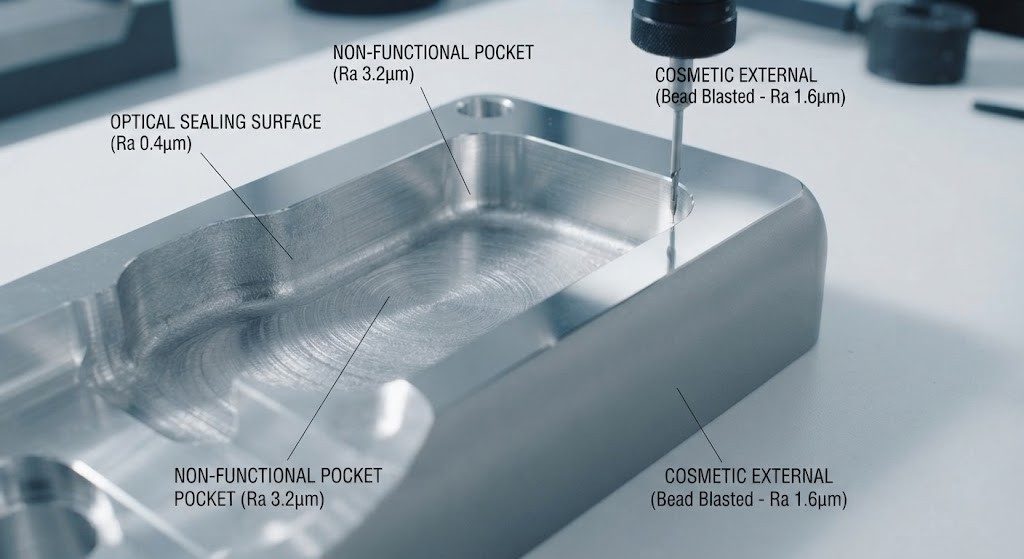
Surface finish requirements can have a significant impact on manufacturing cost. A CNC-machined surface can often be left as-machined when appearance, friction, sealing, or wear requirements do not demand additional treatment.
Possible finishing processes include:
- Polishing
- Bead blasting
- Anodizing
- Powder coating
- Plating
- Brushing
Avoid Applying One Surface Finish Requirement to the Entire Part
If only a sealing surface requires a specific finish, specify that requirement on the relevant surface rather than applying it to every face. This prevents unnecessary secondary processing.
For example:
- Functional sealing surface: controlled surface roughness
- Internal non-functional surface: standard as-machined finish
This approach can reduce both cost and production time.
Choose Materials With Machinability in Mind
The same geometry can have very different manufacturing characteristics depending on the material. JTR Machine’s CNC machining capabilities cover a wide range of engineering materials, including aluminum alloys, stainless steels, engineering plastics, titanium, and other materials used for precision components.
Aluminum
Common CNC machining grades include:
- 6061-T6
- 7075-T6
- 2024
Aluminum generally offers excellent machinability and a high strength-to-weight ratio, making it widely used for prototypes, automation components, aerospace parts, housings, and structural components.
Stainless Steel
Common choices include:
- 303
- 304
- 316L
- 17-4 PH
Stainless steel selection should consider corrosion resistance, strength, heat treatment, and machinability.
Engineering Plastics
Materials such as:
- PEEK
- Delrin
- Nylon
- PTFE
- Ultem
can be excellent choices when low weight, chemical resistance, electrical insulation, or special mechanical properties are required. However, plastics can behave differently from metals because of thermal expansion, moisture absorption, and lower stiffness.
Difficult-to-Machine Materials
Titanium and nickel-based alloys such as Inconel require greater attention to:
- Cutting speed
- Tool wear
- Heat management
- Tool rigidity
- Workholding
Therefore, material selection should always be evaluated together with part geometry and required tolerances.
CNC Milling vs. CNC Turning: Design Considerations
CNC milling and CNC turning are not interchangeable processes.
| Design Consideration | CNC Milling | CNC Turning |
| Typical geometry | Prismatic or complex 3D parts | Cylindrical or rotational parts |
| Main tool movement | Multiple linear/rotary axes | Tool relative to rotating workpiece |
| Typical features | Pockets, slots, holes, contours | Shafts, bores, grooves, threads |
| Major DFM concern | Tool access and pocket geometry | Diameter, length and workpiece rigidity |
| Workholding | Vise, fixture or custom tooling | Chuck, collet or soft jaws |
| Complex geometry | 3-axis to 5-axis | Turn-mill for combined features |
Choosing the appropriate process early can reduce unnecessary setups and improve overall manufacturing efficiency. For example, a rotational component containing extensive milling features may benefit from turn-mill machining, while a complex multi-surface component may be better suited to 5-axis CNC machining.
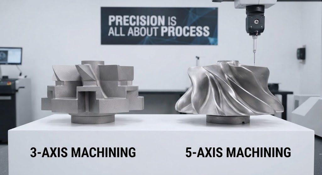
3-Axis vs. 5-Axis CNC Machining
Not every complex-looking part requires 5-axis machining.
3-Axis CNC Machining
3-axis machining is often appropriate for:
- Prismatic components
- Accessible pockets
- Plates
- Brackets
- Housings
- Components that can be machined efficiently in limited orientations
It can provide an economical solution when the geometry is straightforward.
5-Axis CNC Machining
5-axis machining becomes more valuable when a part contains:
- Multiple angled surfaces
- Complex 3D contours
- Difficult-to-access features
- Deep cavities
- Multiple surfaces that would otherwise require separate setups
One major advantage is the ability to access multiple surfaces while reducing repositioning. However, 5-axis machining should be selected because the geometry or production strategy requires it—not simply because it is technically more advanced. The correct process is the one that meets functional requirements at an appropriate manufacturing cost.
How CNC DFM Decisions Affect Manufacturing Cost
CNC machining cost is strongly influenced by geometry. A design that requires more cutting time, more setups, special tooling, or additional inspection will generally cost more.
| Design Decision | Potential Cost Impact |
| Very small internal radius | Smaller tooling and longer machining time |
| Deep narrow pocket | Longer tools and slower cutting |
| Very thin wall | Lower cutting parameters and additional finishing |
| Tight tolerance | Additional machining and inspection |
| Non-standard thread | Special tooling |
| Complex undercut | Additional machining process |
| Multiple setups | Higher setup and alignment cost |
| Premium surface finish | Additional finishing |
| Difficult material | Higher tooling and machining requirements |
The key principle is:
The most economical CNC part is not necessarily the part with the simplest geometry. It is the part that achieves the required function without unnecessary manufacturing complexity.
Common CNC Design Mistakes Engineers Should Avoid
| Mistakes | Description | Better approach |
| Designing perfectly sharp internal corners | Standard milling cutters cannot produce perfectly sharp internal corners. | Use an appropriate internal radius. |
| Making walls thinner than necessary | Thin walls are susceptible to vibration and deformation. | Increase thickness or add structural support where possible. |
| Creating deep, narrow pockets | These often require long, flexible tools. | Increase pocket width, reduce depth, or modify the geometry. |
| Using unusual hole sizes | Special tooling can increase cost. | Use standard drill sizes where function permits. |
| Applying tight tolerances everywhere | Not every feature requires precision machining. | Identify functional dimensions and apply tight tolerances selectively. |
| Ignoring workholding | A geometrically machinable component may still be difficult to fixture. | Provide stable datum and clamping surfaces. |
| Ignoring workholding | A geometrically machinable component may still be difficult to fixture. | Provide stable datum and clamping surfaces. |
| Adding unnecessary undercuts | Undercuts may require special tools or additional processes. | Eliminate non-functional undercuts whenever possible. |
| Specifying premium surface finish everywhere | Additional finishing increases cost. | Specify enhanced finish only on functional or cosmetic surfaces that require it. |
| Ignoring material behavior | Different materials respond differently to cutting forces and heat. | Evaluate geometry and material together. |
| Providing incomplete drawings | A 3D model may show geometry but not always communicate manufacturing intent. | Provide a clear drawing with material, tolerances, surface finish, threads, GD&T, and other critical requirements. |
How to Prepare CAD Files for CNC Machining
A high-quality CAD package makes quotation and manufacturing more efficient.
3D CAD Files
Commonly used formats include:
- STEP / STP
- IGES / IGS
- Parasolid
A 3D model communicates the physical geometry of the part.
2D Engineering Drawings
A drawing should communicate manufacturing requirements that may not be fully defined by the 3D model. Important information includes:
- Material and grade
- Critical dimensions
- General tolerances
- GD&T
- Surface finish
- Thread specifications
- Heat treatment
- Surface treatment
- Inspection requirements
- Revision level
A useful engineering principle is: The 3D model defines the geometry; the technical drawing defines the manufacturing intent. For complex parts, providing both can significantly reduce ambiguity during quotation and production.
CNC DFM Checklist Before Requesting a Quote
Before sending a CNC part to a manufacturer, engineers can review the following checklist.
| Geometry | 1. Internal corners have practical radii 2. Walls are sufficiently rigid 3. Deep pockets have been reviewed 4. Undercuts are functionally necessary 5. Critical features are accessible 6. Part orientation has been considered |
| Holes and Threads | 1. Standard hole sizes are used where possible 2. Hole depths are practical 3. Thread standards are clearly specified 4. Blind holes provide sufficient clearance 5. Critical holes have appropriate tolerances |
| Tolerances | 1. Critical dimensions are clearly identified 2. Tight tolerances are functionally justified 3. GD&T is used where appropriate 4. Datum references are clearly defined 5. Assembly tolerance stack-up has been considered |
| Manufacturing | 1. Material and grade are specified 2. Surface finish requirements are clear 3. Secondary finishing requirements are defined 4. Number of setups has been considered 5. Workholding requirements are practical |
| Documentation | 1. 3D CAD file is available 2. 2D drawing is available where necessary 3. Revision information is included 4. Required quantity is specified 5. Inspection requirements are defined |
What Engineers Should Discuss With a CNC Machining Supplier
DFM works best as a collaboration between design and manufacturing teams. Before production, engineers should discuss:
- Material: Is the specified alloy or plastic readily machinable for the required geometry?
- Tolerance: Which dimensions are truly critical to function?
- Surface Finish: Which surfaces require special treatment?
- Machining Process: Would 3-axis, 4-axis, 5-axis, turning, turn-mill, or another process be most appropriate?
- Workholding: Can the part be securely held without deforming critical surfaces?
- Inspection: Which dimensions require CMM or specialized inspection?
- Production Volume: Will the optimal manufacturing strategy change between prototype and production quantities?
A capable CNC manufacturer should be able to identify potential manufacturing risks before machining starts and recommend practical alternatives when appropriate.
CNC DFM for Prototypes vs. Production Parts
DFM requirements can change depending on production volume. For a one-off prototype, a slightly more complex setup may be acceptable if it allows the part to be produced quickly. For hundreds or thousands of parts, however, a small reduction in cycle time can produce significant savings across the production run.
For production quantities, engineers should pay particular attention to:
- Setup reduction
- Standard tooling
- Repeatable workholding
- Cycle time
- Inspection strategy
- Tool life
- Process stability
This is why design optimization should consider the intended production volume rather than focusing only on whether the first prototype can be machined.
Frequently Asked Questions About CNC Machining Design Guidelines
Q1: What are the most important CNC machining design guidelines?
The most important considerations are tool accessibility, wall thickness, internal corner radius, pocket depth, hole and thread design, tolerances, workholding, material selection, surface finish and the number of machining setups.
Q2: What is the minimum wall thickness for CNC machining?
There is no single minimum value that applies to every CNC part. For many metal components, 1.0–1.5 mm can be considered a practical starting range for thin walls, but wall height, material, geometry, tooling and machine capability must also be considered.
Q3: Can CNC machining produce sharp internal corners?
Standard CNC milling generally cannot produce perfectly sharp internal corners because round cutting tools leave a radius. Sharp corners may require very small cutters or secondary processes such as EDM.
Q4: How deep can a CNC pocket be?
Pocket depth depends on width, tool diameter, tool length, material and machine rigidity. Deep and narrow pockets are generally more difficult than shallow and wide pockets because longer tools are more susceptible to deflection and vibration.
Q5: What hole size is best for CNC machining?
Standard drill sizes are generally preferable because standard tools are readily available. The appropriate size still depends on the fastener, fit, function and required tolerance.
Q6: How does material affect CNC DFM?
Material affects cutting forces, tool wear, heat generation, deformation and achievable machining parameters. A geometry that is easy to machine in aluminum may require significantly different strategies in stainless steel, titanium or engineering plastics.
Q7: When should I use 5-axis CNC machining?
5-axis machining is particularly useful when a component contains multiple angled surfaces, complex contours or difficult-to-access features, or when reducing the number of setups can improve accuracy and efficiency.
Q8: How can CNC design reduce manufacturing cost?
Use standard features, practical corner radii, reasonable tolerances, accessible geometry, stable wall thicknesses, practical pocket depths and fewer machining setups. These changes can reduce tooling, cycle time, setup and inspection requirements.