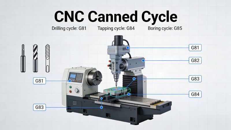
In the domain of Computer Numerical Control (CNC) programming, the efficiency of material removal and hole-making operations is dictated by the strategic application of G-codes. While linear and circular interpolation (G01, G02, G03) form the geometry of a part, CNC canned cycles serve as pre-programmed subroutines that execute complex multi-step motions through a single line of code. This technical analysis examines the operational logic, parameterization, and industrial application of the most critical hole-making cycles: G81, G83, and G84, while emphasizing the necessity of the G80 cancellation command.
The Fundamentals of CNC G Code and Canned Cycle Logic
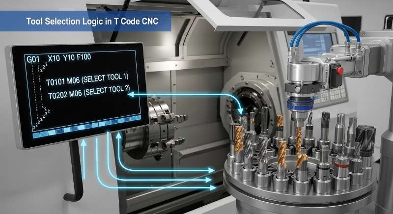
CNC G code functions as the standardized communication protocol between Computer-Aided Manufacturing (CAM) software and the machine control unit (MCU). Within this protocol, canned cycles (G81 through G89) are modal commands. Once a cycle is initiated, the machine will repeat the specified movement at every subsequent X-Y coordinate provided until the cycle is explicitly terminated.
The structural integrity of a canned cycle block typically follows a standardized syntax: GXX X__ Y__ Z__ R__ Q__ P__ F__
- GXX: The specific cycle (e.g., G81, G83).
- X/Y: The coordinate position of the hole center.
- Z: The final depth (absolute position of the hole bottom).
- R: The reference plane (the safety height where feed rate begins).
- Q/P: Incremental depth (for G83) or dwell time (for G82).
- F: The feed rate (velocity of the cutting tool).
The Role of G80 CNC Code in Program Safety
The G80 command is an essential safety protocol used to cancel all active canned cycles. Because these cycles are modal, failure to execute a G80 before a rapid move (G00) can result in the machine attempting to “drill” at the next coordinate instead of simply moving to it. In professional manufacturing environments, G80 is frequently included in the “safety block” at the start of a program to clear any residual modal data from previous operations.
Technical Analysis of the G81 Drilling Cycle
The G81 drilling cycle is the most direct method for hole generation. Its motion sequence consists of three distinct phases:
- Rapid Positioning: The tool moves at maximum traverse speed to the X-Y coordinates.
- Linear Feed: The tool descends at the specified feed rate (F) from the R-plane to the final Z-depth.
- Rapid Retract: Upon reaching the depth, the tool immediately returns to either the R-plane or the initial start height.
Application and Limitations
G81 supports drilling operations for shallow holes, which have D:d ratios that stay under 3:1. G81 serves as the preferred tool for center drilling and spot drilling in 6061 aluminum materials. The tool remains fixed during its downward movement, which prevents any chip removal or coolant flow to the drill tip. The use of G81 for deep hole drilling operations creates a higher possibility of chip accumulation, which results in complete tool breakdown and localized thermal expansion of the workpiece.
Deep Hole Engineering: The G83 CNC Code
The “Peck Drilling Cycle” G83 CNC code provides deep-hole operation support through its recursive retraction feature. G83 enables users to divide total Z-depth into smaller increments through its Q-parameter, which differs from G81’s fixed depth measurement.
Operational Mechanics
In a G83 cycle, the tool drills to the depth of the first Q-increment, then rapidly retracts to the R-plane. This retraction performs two critical functions:
- Chip Evacuation: It pulls the accumulated swarf out of the hole, preventing “bird-nesting” around the drill flute.
- Thermal Management: It allows the flood coolant to reach the bottom of the hole and the drill point, reducing the friction-induced heat that is prevalent when machining high-strength alloys like 7075 aluminum.
The tool backs into the hole after the retract process until it reaches a point that is 0.1mm to 0.5mm short of its previous depth before the next pecking operation begins. The process repeats until workers achieve the targeted Z-coordinate.

Precision Internal Threading: The G84 Tapping Cycle
G84 CNC code is employed in the production of internal threads. The operation necessitates perfect synchronization between the spindle rpm and the feed rate on the Z-axis.
Rigid Tapping vs. Floating Tapping
Modern CNC centers utilize Rigid Tapping, which depends on electronic gearing between the spindle motor and Z-axis servo. The G84 system operates in this mode by making the tool move one thread pitch for each complete spindle rotation.
The feed rate calculation for G84 is critical. In metric systems, the formula is: F=S×P
Where:
- F = Feed rate (mm/min)
- S = Spindle Speed (RPM)
- P = Thread Pitch (mm)
The programmer needs to set the feed rate to 500 mm per minute when he uses an M6x1.0 tap at 500 RPM. Any change to this ratio will result in either stripped threads or a broken tap. The tool will stop when it reaches the Z-depth limit, and the spindle will change its direction while the Z-axis moves back to complete hole exit.
Advanced Control: G98 and G99 Return Levels
A critical component of implementing g81 drilling cycles and other canned commands is the selection of the return level.
- G98 (Return to Initial Level): The tool retracts to the Z-height it occupied before the canned cycle was called. This is used when the tool must clear obstructions, such as clamps or high walls of a fixture, between holes.
- G99 (Return to R-Plane): The tool retracts only to the R-plane. This minimizes “air-cutting” time and is used when the surface between holes is flat and unobstructed.
Technical Data Comparison Table
| Command | Primary Function | Depth Control | Retract Behavior | Common Use Case |
| G81 | Basic Drilling | Continuous | Immediate Rapid | Spot drilling, center holes |
| G82 | Counterboring | Dwell at Bottom | Rapid after P-delay | Flat bottom holes, chamfering |
| G83 | Deep Hole Drilling | Incremental (Q) | Full retract to R-plane | Holes deeper than 3x Diameter |
| G84 | Tapping | Synchronized | Spindle Reverse | Internal thread cutting |
| G73 | High-Speed Peck | Incremental (Q) | Small retract (0.5mm) | Long chips, shallow pecking |

Strategic Implementation in Aluminum Manufacturing
You must use specific G-code methods for programming 6061 and 7075 aluminum materials to achieve precise measurements and proper surface treatment results. Aluminum develops built-up edge (BUE) because the metal fuses to the cutting tool through heat buildup.
- G83 for 7075-T6: Due to the higher zinc content and hardness of 7075 compared to 6061, heat generation is more significant. Utilizing G83 with a smaller Q-value ensures consistent cooling.
- Feed Rate Optimization in G84: Aluminum requires high-quality lubrication during tapping. Utilizing G84 in conjunction with high-pressure through-spindle coolant (M08) is standard practice to prevent thread galling.
- G80 Verification: In multi-tool operations, always verify that G80 follows the last coordinate of a drilling sequence to ensure the subsequent tool change (M06) and rapid positioning occur without interference from modal cycle logic.
Manufacturers achieve optimal cycle times and tool life preservation through their masterful control of CNC g code technical details, which include the G81 to G83 and G84 transition. Programmers create dependable processes for intricate industrial components by learning the mechanical needs of chip removal and spindle synchronization. The safe operation of CNC machines depends on G80 usage, which establishes a framework for predictable machine performance.
Technical References:
1. International Standards (ISO)
The universal foundation for G-code (often called “ISO Programming”) is defined by the following standard:
ISO 6983-1:2009: Automation systems and integration — Numerical control of machines — Program format and definitions of address words.
Detailed Preview (via ANSI) — This PDF contains the technical definitions for preparatory functions (G) and miscellaneous functions (M).
2. Machine Control Manuals (Fanuc & Haas)
These are the industry-standard “bibles” for implementing G81, G83, and G84 in real-world environments.
Fanuc Series 30i/31i/32i-Model B (Programming Manual):
Fanuc CNC Plus Catalog (Technical Specs) — Covers high-speed cycle technologies.
Haas Automation (Mill Programming Workbook):
Haas G-Code List (Official Site) — A live, searchable index of all Haas-supported G-codes including G81 and G84.
Haas Mill Programming Workbook (PDF) — Detailed exercises on Canned Cycles starting on Page 81.
3. Engineering & Material Data
For calculating speeds and feeds (especially for 6061 and 7075 Aluminum), these are the primary technical sources:
Machinery’s Handbook (31st Edition):
Digital Archive / Pocket Companion (PDF) — Reference for “Speeds and Feeds” and “Drilling/Tapping” constants.
Speeds and Feeds Calculator (Technical Tables):
University of Florida – Design Lab Data — Provides the F=S×P formulas and aluminum-specific constants referenced in the article.