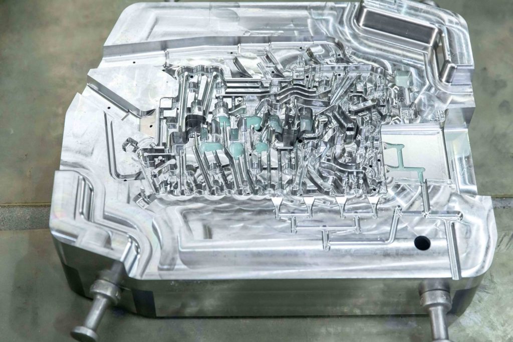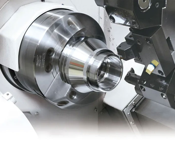
In the realm of high-end aerospace manufacturing, the machining of structural parts made from titanium alloys — more specifically Ti-6Al-4V — brings up some pretty serious metallurgical plus mechanical snags. When the engineering drawings require a dimensional allowance of ±0.005 mm (that is, ±5 μm), the usual CNC machining workflow pretty much stops being relevant. Titanium behaves with a low elastic stiffness, weak heat transfer, high chemical reactivity when things get hot, and it also shows a strong habit of work hardening. These native material properties inherently induce excessive cutting forces, localized thermal concentration, and part deflection.
Aerospace CNC machining overcomes the limitations of a single machining center by employing a fully integrated, closed-loop manufacturing system that integrates environment control, machine tool kinematics, advanced tool geometry, specialised workholding, and in-process metrology to achieve repeatable micron-level accuracy.
Eliminating Physical Variables: Environmental Control & Machine Rigidity
When targeting a ±5 μm dimensional window, ambient temperature fluctuations represent a primary source of volumetric error. Thermal expansion coefficients dictate that even minor temperature deltas will cause measurable dimensional drift in both the workpiece and the machine tool casting.
1. Micro-Climate and Coolant Stabilization
The precision cells need to be located in an isolated and climate-controlled machine shop floor with dedicated HVAC systems to maintain an ambient temperature of 20 ℃±0.5 ℃(68 ℉±0.9 ℉) to minimise thermal drift. Crucially, the metalworking fluid (coolant) delivery system needs to be connected to an industrial chiller unit that is capable of controlling the fluid temperature to within ±0.1 ℃ of the machine bed’s baseline temperature. This prevents the localized thermal expansion or contraction of the titanium substrate during material removal.
2. Machine Tool Kinematics and Volumetric Accuracy
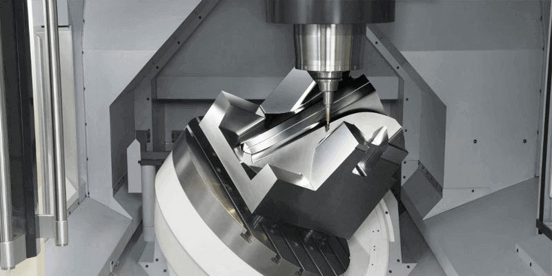
Executing aerospace precision machining at this threshold requires ultra-high-precision 5-axis machining centers engineered with high static and dynamic stiffness.
- Thermal Symmetry: The machine tool structure must incorporate symmetrical castings to ensure that any inevitable thermal growth occurs uniformly and away from the tool-workpiece interface.
- Direct Drive Motors & Linear Guides: Axis actuation must rely on direct-drive technology to eliminate backlash.
- Closed-Loop Feedback: The real-time position tracking must be managed by absolute linear optical scales with nanometric resolution (e.g. Heidenhain encoders) directly connected to the CNC controller, free from mechanical errors of the ballscrews.
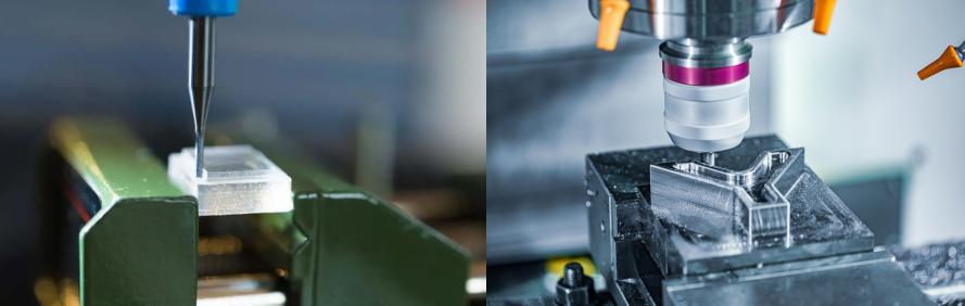
Advanced Tooling & Cutting Strategies for CNC Machining for Aerospace Parts
The poor thermal conductivity of Ti-6Al-4V dictates that approximately 90% of the generated cutting heat is directed into the cutting edge rather than being evacuated via the chip. This localized thermal concentration accelerates tool wear and induces surface-integrity defects on the part.
1. Stress Relief Cycles and Stock Management
Uncontrolled residual stresses from raw stock or aggressive roughing will cause immediate part warping upon clamping release. The process routing for critical components must bifurcate the roughing and finishing operations:
Rough Machining⟶Vacuum Stress-Relief Annealing⟶Semi-Finishing⟶Final Micro-Finishing
During the final finishing pass, the depth of cut (ap) is restricted to 0.02 mm∼0.05 mm. Minimizing the radial engagement drastically reduces cutting forces and curtails the elastic deflection of the component.
2. Tool Selection and Geometry
Our engineering team utilizes ultra-fine-grained solid carbide substrates characterized by high hot-hardness and toughness.
- Coatings: Coatings containing titanium (such as TiN or TiAlN) must be avoided due to the chemical affinity between the coating and the substrate, which induces adhesive wear and built-up edge (BUE). Polished, non-coated tools or specialized CrN/DLC coatings are deployed instead.
- Geometry: The tooling must feature a sharp, positive rake angle (10°∼15°) and a high helix angle to shear the material cleanly, reducing the mechanical load.
- Dynamics: Variable-pitch and variable-helix end mills are mandatory to disrupt harmonic frequencies, thereby suppressing regenerative chatter that degrades surface finish and dimensional consistency.
3. High-Pressure Fluid Management
High tolerance zones require chip evacuation and temperature control that standard flood cooling cannot provide. The setup must have a Through-Spindle Coolant (TSC) system with a minimum threshold of 70 bar (1,015 psi). This high-pressure delivery serves three functions, instant quenching of the cutting edge, breaking up the ductile titanium chips into manageable segments, and evacuation of the chips from the cut zone to prevent recutting.
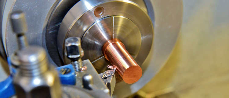
Managing Elastic Deformation: Smart Clamping Solutions
Titanium’s modulus of elasticity is about 110 GPa, about half that of structural steel. Therefore, titanium will have twice the mechanical deflection under the same clamping pressures. During the cycle, the localised forces from traditional mechanical vises or hard jaws deform thin-walled geometries, with the material springing back when released, immediately violating the ±0.005 mm constraint.
1. Advanced Workholding Methodologies
To distribute structural loads evenly, our shop employs custom vacuum chucks or low-distortion hydraulic fixtures configured for specific part profiles. For extremely intricate or thin-walled geometries, phase-change workholding (such as cryogenic or freeze clamping systems) is utilized to encapsulate the component in ice, providing uniform support against cutting forces without applying localized mechanical pressure.
2. Datum Consistency
To maintain structural alignment across multiple operations or machine handoffs, components are integrated with zero-point clamping systems. The pull-stud receivers embedded in the fixture base ensure a mechanical repeatability of <2μm, isolating the setup from human error during part flipping or transferring.
In-Process Metrology and Closed-Loop Feedback
Predictive programming alone cannot account for dynamic variables such as micro-tool wear or localized machine casting movement over extended cycle times. Machining high-value CNC machining for aerospace parts requires real-time, in-situ validation.
1. On-Machine Probing Cycles
Prior to executing the final dimensional finish pass, the CNC program pauses to initiate an on-machine probing routine utilizing a strain-gauge touch-trigger probe (e.g., Renishaw OMP series). The probe samples critical reference datums and semi-finished surfaces directly within the machine envelope.
2. Adaptive Compensation Loops
The measured spatial coordinates are fed back to the CNC controller via macro variables. The controller evaluates the variance between the actual semi-finished dimension and the nominal blueprint values. It then automatically updates the tool wear offsets (D-values and H-values) to correct for the exact micro-wear profile of the end mill prior to running the final finish path. This software-driven feedback loop effectively eliminates manual operator intervention.
Verification: The CMM Protocol in Aerospace CNC Machining
In ultra-precision manufacturing, proving that a dimension meets a ±0.005 mm requirement is as complex as executing the cut. Metrology principles dictate that the measuring instrument must possess an uncertainty profile at least one-fifth to one-tenth of the total tolerance band being verified.
1. Part Conditioning Protocols
Components cannot be measured immediately upon completion of the machining cycle. They have to follow a strict stabilisation protocol in a dedicated metrology laboratory, which is kept at a constant temperature of 20 ℃±0.1 ℃. A minimum of 12 to 24 hours (mass dependent) soaking in this environment is required for the parts to allow for total thermal equilibrium and the relief of any latent mechanical stresses.
2. High-Accuracy Metrology Equipment
Final dimensional inspection is conducted exclusively via high-accuracy Coordinate Measuring Machines (CMMs) equipped with analog scanning probes. These systems must feature a maximum permissible error (MPEE) profile of:
MPEE≤0.5μm+L/1000
This level of measurement resolution guarantees that the data points acquired are statistically valid, establishing clear traceability metrics for aerospace compliance records.

Operational Configuration Matrix
The technical divergence between standard commercial milling setups and an optimized aerospace production cell targeting micron-level tolerances is outlined in the matrix below:
| Operational Variable | Standard Commercial Machining | Optimized Aerospace Precision Machining |
| Ambient Thermal Regulation | ±2.0℃ variance allowed | Regulated to ±0.5∘C (Lab: ±0.1℃) |
| Coolant Temperature Control | Unregulated flood cooling | Chiller-stabilized TSC at ≥70 bar |
| Positioning Feedback | Rotary encoder on servo motor | Direct-path linear optical scales (Nanometer scale) |
| Fixture Mechanism | Manual/Hydraulic hard jaw clamping | Vacuum, cryogenic, or zero-point systems |
| Dimensional Compensation | Offline manual micrometric updates | Automated in-process touch probe feedback loops |
| Inspection Standard | Manual gauges / Standard CMM | Extended thermal soaking + Sub-micron CMM verification |
An aerospace facility can achieve consistently titanium components within a ±0.005 mm design window by standardising these engineering controls and neutralising the thermodynamic and mechanical variables of the process.