

Designing a custom sheet metal enclosure is harder than it looks on screen—a flange that’s 2mm too narrow, a ventilation slot placed too close to a bend line, or a missing bend relief can cascade into warped panels, failed IP seals, and costly rework.
This guide discusses the precise choices that have the most impact on enclosure quality: bend geometry, hole placement, and the design errors most common to our engineers’ review of submitted files in sheet metal fabrication.
Key Functional Requirements of Sheet Metal Enclosures
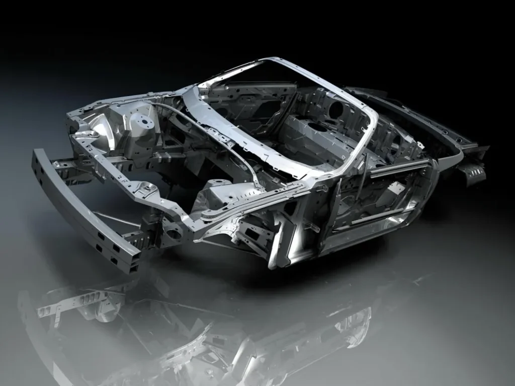
Before you work through the geometry principles, you need to understand why enclosures need greater precision than basic sheet metal pieces. A good enclosure has to please at the same time:
- IP-rated sealing (e.g., IP54, IP65): demands tight, gapless seams at every corner—bend accuracy directly determines the existence of those gaps.
- EMI shielding: electromagnetic confinement in industrial electronics housings can be compromised by even small panel gaps.
- Structural rigidity: panels must be able to withstand deflection from the component load and repetitive cycling of the door or cover.
Each criteria is directly related to bending precision and hole location. If the bend is off 1-2 degrees, seam gaps open. If a hole is too close to a bend the flange will be distorted and covers will not lie flush. These are functional specs, not fabrication preferences.
Essential Sheet Metal Bending Design Guidelines
Most results on bending of enclosures hinge on two design decisions: the suitability of the radius choice for the material, and whether the flanges are sized to avoid post-bending instability. Nailing both avoids the most likely structural and assembly problems downstream.
Mastering the Bend Radius for Different Materials
One of the most misunderstood elements in sheet metal fabrication design is the interior bend radius. If too tight, the outer surface splits; if too generous, you lose dimensional control over the finished form.
2.0X material thickness is a good starting point for aluminum (more ductile than mild steel). And 1.5X material thickness is a popular starting point inside bend radius for mild steel. These are direction of travel numbers, actual minimums depend on temper, thickness range and tooling available.
One exception worth bringing out specifically, and one that’s well-established, is 6061-T6 aluminum. The material work-hardens during forming and a radius of less than 1.5-2T is a reliable path to cracking at enclosure corners, even if other aluminum alloys can handle tighter bends. For stainless steel (304/316) the effect of work hardening is even more obvious. Minimum 1.5-2T is a reasonable safety margin, not a conservative preference.
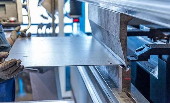
The most reliable approach is to confirm your radius spec against the fabricator’s press brake tooling library before locking corner geometry. A radius that requires non-standard tooling adds lead time regardless of whether it is physically possible or not.
Designing Stable Flanges and Mounting Edges for Enclosures
Flange width is one of the most commonly under-specified characteristics in enclosure designs submitted. The flange is too narrow and this triggers a cascade of problems:
- Panel rigidity: short flanges are likely to flex under lateral strain causing the enclosure to rack, a particular problem for control boxes and industrial PC housings.
- Screw mounting: sufficient material for clearance hole, and sufficient edge distance (usually 2x hole diameter from nearest edge).
- Cover and door alignment: enclosures with panel-mount connectors or hinged doors are very sensitive to flange flatness.
- Assembly clearance: tight inner flanges can interfere with mounting hardware for the PCB or internal wirings.
Industry guides always indicate 4× material thickness as a feasible minimum flange width for most materials. The extra material is justified for load-bearing side panels on industrial cabinets or electrical enclosures with bigger flanges and strengthening secondary bends.
Best Practices for Hole Placement and Cutouts
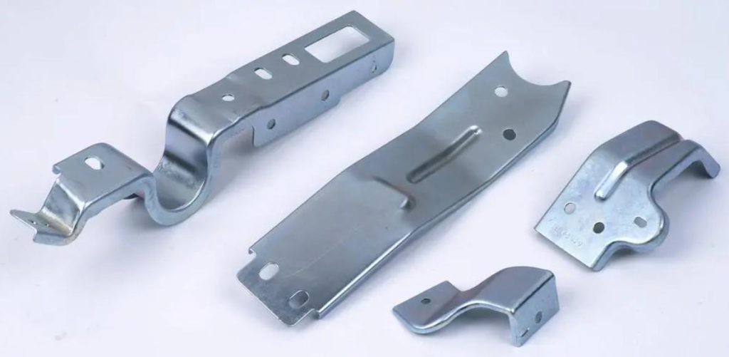
Holes and cutouts add geometry for the metal to work around during shaping. If a feature is too close to a bend line, the plastic deformation pulls the material out, pushing the hole out of round and distorting the panel around it.
Designers must keep cuts out of the bend deformation zone to maintain structural integrity and to avoid flush-mounting concerns (particularly for connectors or ventilation arrays). The minimums depend on hole size. The Sheet Metal Design Handbook shows safe distances from the edge of the hole to the bend line as:
- Standard Holes: Minimum distance = 2.5T + R (where T = material thickness, R = bend radius). While some manuals allow 2T+R for holes under 1”, but setting 2.5T+R everywhere avoids out-of-round errors.
- Long Slots and Cutouts: Minimum distance = 4T + R. The free edge of a long slot is a key stress concentrator in shaping. Closer spacing will almost probably mean a wavy panel face.
Design Tip: If space is limited and a cutout has to go over or next to a bend line, you’ll need to put in a relief cut or notch across the bend line before you form it.
Common Enclosure Design Mistakes Engineers Should Avoid
These are the four difficulties that seem to happen most commonly from our team’s frequent analysis of the CAD files:
| Mistake | Fix |
| Inconsistent wall thickness across panels | Use a single gauge throughout; mixed thicknesses require separate tooling setups and increase cost |
| Missing bend reliefs at corner intersections | Add a relief notch (width ≥ 1T, depth ≥ T + R) wherever two bend lines meet, to prevent tearing during forming |
| Holes inside the deformation zone near bends | Follow the 2.5T + R minimum for holes; 4T + R for slots |
| Ignoring surface finishing allowances | Powder coating: typical applied thickness 60–80 µm per coat; Type II anodizing: 5–25 µm. Both affect thread engagement and mating fits if not accounted for in the original design |
Note: These values are only guidelines and may need adjustment based on the specific requirements of the part.
Ready to Elevate the Quality of Your Metal Enclosures?
Good enclosure design is a collaboration between design intent and manufacturing reality. The most reliable enclosures aren’t the most complex—they’re the ones where every bend radius, hole clearance, and flange width was thought through with production in mind.
JTR’s engineering staff evaluates all submitted files for DFM concerns to optimize the part design prior to any part going into production. Upload your CAD files or contact JTR’s engineering team for a free manufacturability review and custom material selection. If you have any project requirements, please feel free to contact us.
FAQs
Q1: What is the minimum distance between bends in sheet metal?
A1: Keep parallel bend lines at least 4× the material thickness apart as a practical design minimum for enclosures. Narrower spacing can create tooling interference during forming and may also reduce flange stability and dimensional consistency.
Q2: Why do holes deform near bends?
A2: Bending plastically deforms the material in the bend zone, stretching the outer surface and compressing the inner. Any hole placed too close to the bend line—typically within about 2.5× material thickness plus bend radius—can become distorted as the surrounding material flows during forming.
Q3: Which material is best for custom sheet metal enclosures?
A3: For most electronics enclosures, aluminum 5052 is the practical default because it bends cleanly, anodizes well, and keeps weight down. If your enclosure requires welded construction, outdoor durability, or higher shielding effectiveness, 304 stainless is often the stronger choice. However, its work-hardening behavior demands careful attention to bend radius, since stainless cracking failures commonly begin at improperly designed bends.