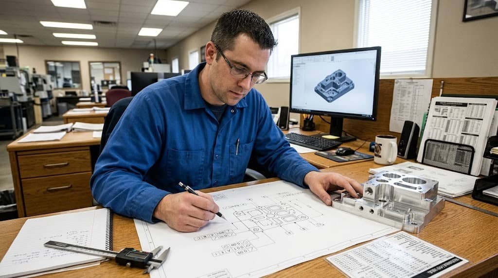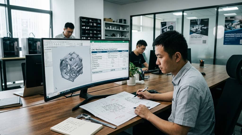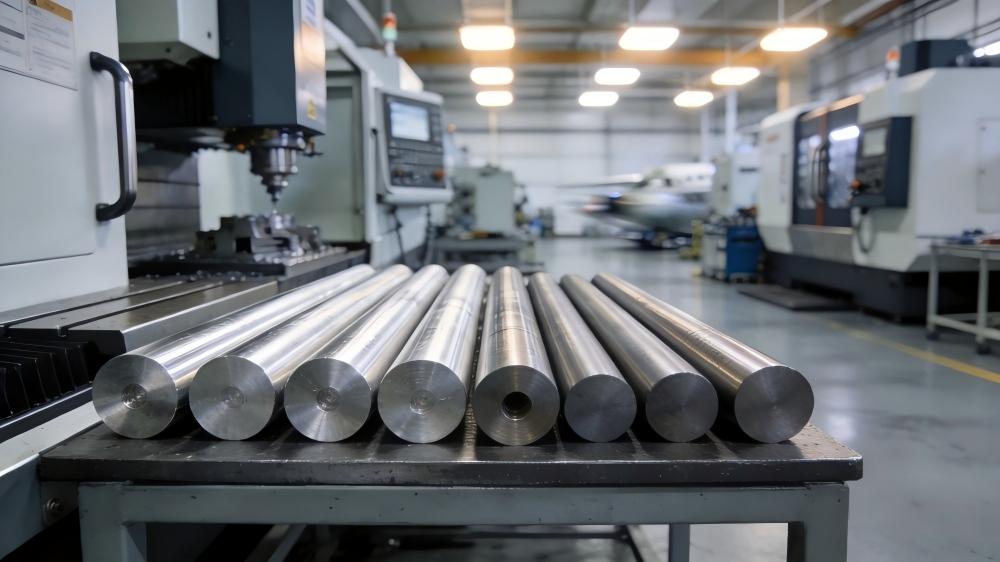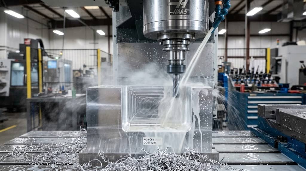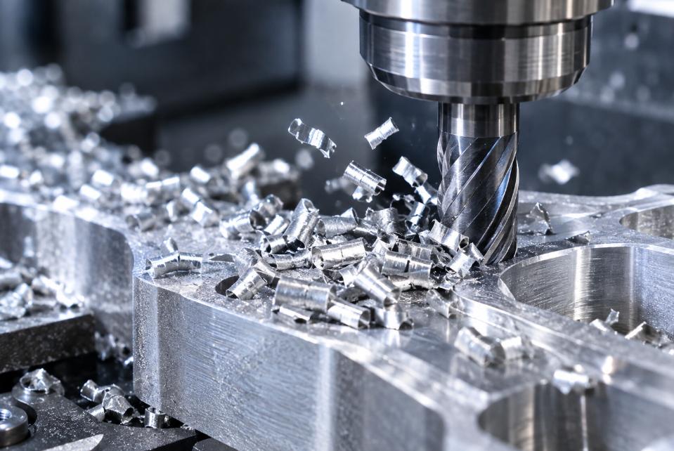


Due to residual stress, cutting force, heat accumulation, excessive clamping pressure, and insufficient support of workpiece fixtures, aluminum parts may deform during CNC machining. When components have thin walls, narrow heat sinks, deep pits, or precision mounting surfaces, these risks become more difficult to control.
Preventing deformation of precision aluminium parts requires more than adjustment of the cutting parameters. The process path, chip removal, datum transfer, surfacing, and after-machining process should be designed as a system. In this article, we are going to take a look at a real-world CNC milling project from JTR Machine and 5 practical controls for the deformation risks of a precision aluminium part.
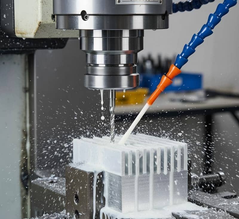
Project Overview: CNC Machining an Al 5083 Cooling Component
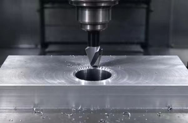
In this project, JTR Machine processed a compact aluminum component featuring a mounting surface, recessed areas, countersunk holes, locating steps, and multiple narrow cooling fins.
The part required machining on both sides, followed by black anodizing. Its thin fin geometry and precision mounting features made dimensional stability a key manufacturing concern.
Project specifications:
| Item | Project Details |
| Material | Al 5083 |
| Part dimensions | 42 × 91 × 25 mm |
| Production quantity | 30 pieces |
| Machining process | CNC milling |
| Dimensional tolerance | ±0.05 mm for all dimensions |
| Surface treatment | Black anodizing |
The machining sequence included:
- Preparing the Al 5083 material and establishing the initial datum.
- Rough milling the top mounting surface, external profile, and recessed pocket.
- Repositioning the component with a dedicated fixture to machine the opposite side.
- Milling the closely spaced cooling fins.
- Finishing countersunk holes and locating steps.
- Deburring and cleaning the machined component.
- Applying black anodizing.
- Performing secondary hole cleaning after anodizing as required by the project process.
The main challenge was maintaining dimensional consistency across the entire component, particularly around the thin cooling fins, mounting surface, and finished holes.
Why Does Aluminum Deform During CNC Machining?
The mechanical processing of aluminum is relatively easy, but its mechanical and thermal properties may pose challenges to size control.
The factors that cause deformation include:
- Residual stress: The stress that originally existed in the raw material is redistributed during the processing due to the removal of the material, which may cause the part to bend or twist.
- Cutting force: The pressure applied by the tool may cause deflection of thin-walled or narrow rib structures, especially when the remaining material lacks rigidity.
- Heat accumulation: The heat generated by cutting can cause local thermal expansion; When the parts cool down, their dimensions may change.
- Clamping force: Excessive or uneven pressure on the fixture can cause distortion of the parts during the machining process; This kind of deformation often appears after releasing the fixture.
- Poor chip removal: The accumulation of chips can interfere with the cutting process, increase friction, and damage the already machined surface.
Studies of machining of thin-wall aluminium indicate that part deformation is mainly caused by the pre-existing residual stress before machining and the residual stress introduced in the machining process. So, deformation control should be taken into account in the process planning stage rather than at the final inspection.
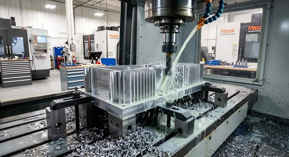
Five CNC Machining Controls JTR Machine Uses to Reduce Deformation Risks
1. Thin-Wall Cooling Fin Machining: Control Cutting Forces and Vibration
As these thin cooling fins become less “stiff” in the machining process, they become susceptible to chatter, tool deflection, and permanent bending. In this project, the bottom fins were closely spaced and had to be milled carefully. Aggressive cutting could cause vibration, poor surface quality, or dimensional variation between fins.
JTR Machine addressed this challenge through a geometry-specific machining strategy:
- Select aluminum-compatible cutting tools suitable for the fin geometry.
- Use high-speed cutting with controlled cutting engagement.
- Remove material through multiple shallow passes rather than excessive cutting depth.
- Apply a suitable toolpath and cutting direction to reduce unnecessary lateral loading.
- Avoid excessive tool overhang where the setup allows.
The purpose is not simply to increase cutting speed. The cutting strategy must balance tool engagement, heat generation, vibration, and the stiffness of the remaining material.
2. Chip Evacuation: Keep Narrow Gaps Clear During Milling
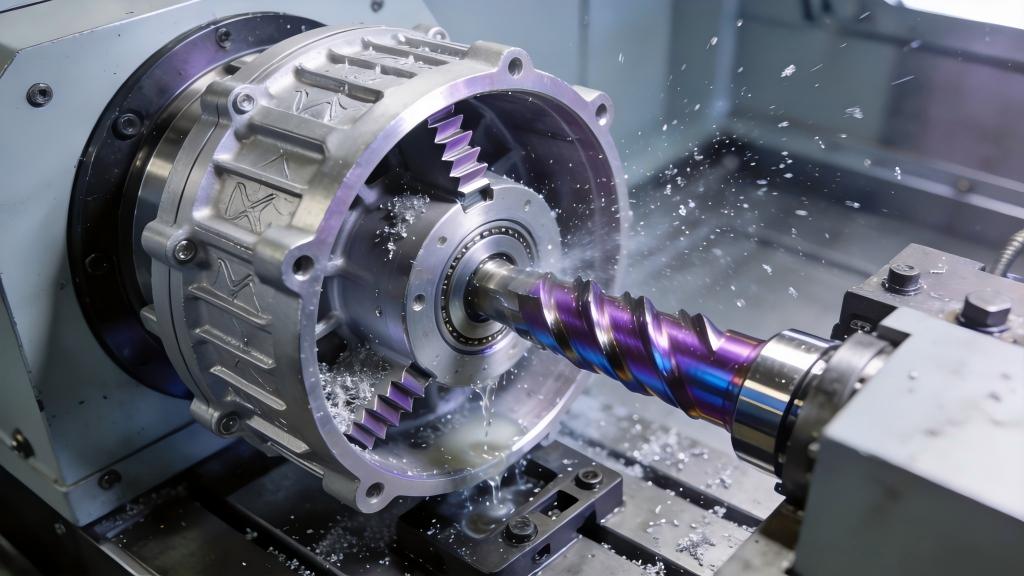
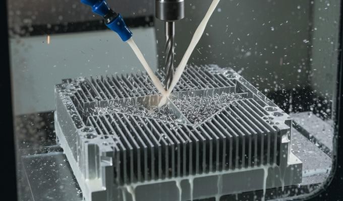
Closely spaced cooling fins create narrow channels where chips can accumulate. If chips remain in these gaps, they may be recut by the tool, increasing friction and potentially damaging the fin surfaces. Poor chip removal can also affect machining consistency.
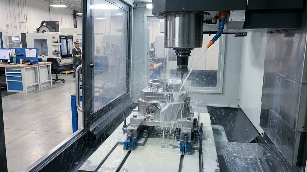
For this component, JTR Machine used continuous high-pressure air assistance to help remove chips from the narrow fin channels during milling.
Effective chip evacuation helps to:
- Reduce chip recutting.
- Prevent chip accumulation between fins.
- Maintain a more stable cutting condition.
- Protect machined surfaces from chip-related scratches.
- Improve process consistency across repeated operations.
For components with narrow slots, deep pockets, or dense fin structures, chip evacuation should be considered during toolpath and fixture planning, not treated as a separate cleanup task.
3. Precision Workholding: Maintain Position Accuracy During Two-Sided Machining
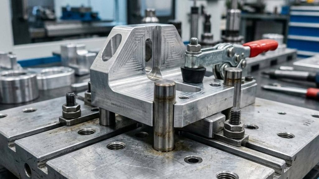
Machining both sides of a component introduces another risk: datum displacement during repositioning. If the part is not located consistently after flipping, the second operation may introduce positional errors between the cooling fins, holes, mounting features, and external profile.
JTR Machine controlled this risk by establishing the first-side datum and using locating pins and a locking fixture to support repeatable positioning during the second setup.
The workholding strategy focused on three points:
- Establish a reliable reference: Use the first machining operation to create the datum features needed for subsequent positioning.
- Control repositioning: Use locating pins to reduce variation when the component is flipped.
- Apply appropriate clamping force: Secure the part without introducing unnecessary stress into thin or unsupported areas.
A stable fixture is essential for maintaining the relationship between features machined from different sides. However, positioning accuracy and clamping pressure must be controlled together: a repeatable setup should not come at the expense of part deformation.
4. Mounting Surface Flatness: Finish Critical Surfaces at the Right Stage
Mounting surfaces are functional rather than cosmetic. An uneven mounting surface can prevent the component from making proper contact with the mating assembly. Poor contact can also compromise the desired thermal interface for a cooling component.
JTR Machine considered the mounting surface a critical dimensional feature for this project and planned to finish this surface after major material-removal operations. It minimises the chance of spoiling the finished surface with subsequent heavy milling or repositioning.
The practical controls include:
- Identify critical mounting and contact surfaces from the engineering drawing.
- Complete major roughing operations before final surface finishing.
- Maintain stable support during finishing.
- Avoid unnecessary clamping stress.
- Inspect the finished surface against the specified drawing requirements.
Finishing a critical surface at the right stage is just as important as selecting the correct cutting tool.
5. Anodizing Dimensional Compensation: Control Holes and Fitting Features
Black anodizing improves the surface characteristics and appearance of aluminum components, but the process can also change dimensions. Anodizing converts the aluminum surface into an oxide coating. The coating occupies space, and its dimensional effect depends on the alloy, coating type, thickness, and process conditions.
For holes and precision fitting features, coating growth can reduce the available opening. The actual dimensional change should therefore be assessed with the anodizing supplier and the specified coating requirements.
For this project, JTR Machine incorporated the anodizing stage into the dimensional-control plan and performed secondary hole cleaning after anodizing as part of the actual production process. This operation helps bring the specified holes into the required final condition after surface treatment. It must be controlled carefully to avoid damaging the anodized surface or changing dimensions beyond the drawing tolerance.
A suitable process plan should define:
- Which holes require post-anodizing cleaning.
- The required final hole dimensions.
- The anodizing coating specification.
- Whether masking or other surface-protection measures are needed.
- How the finished holes will be inspected.
The Aluminum Anodizers Council explains that anodizing changes component dimensions and that the amount depends on process conditions and alloy. Its technical guidance is useful when planning dimensional allowances for anodized parts.
How Should Manufacturers Verify CNC Machining Accuracy?
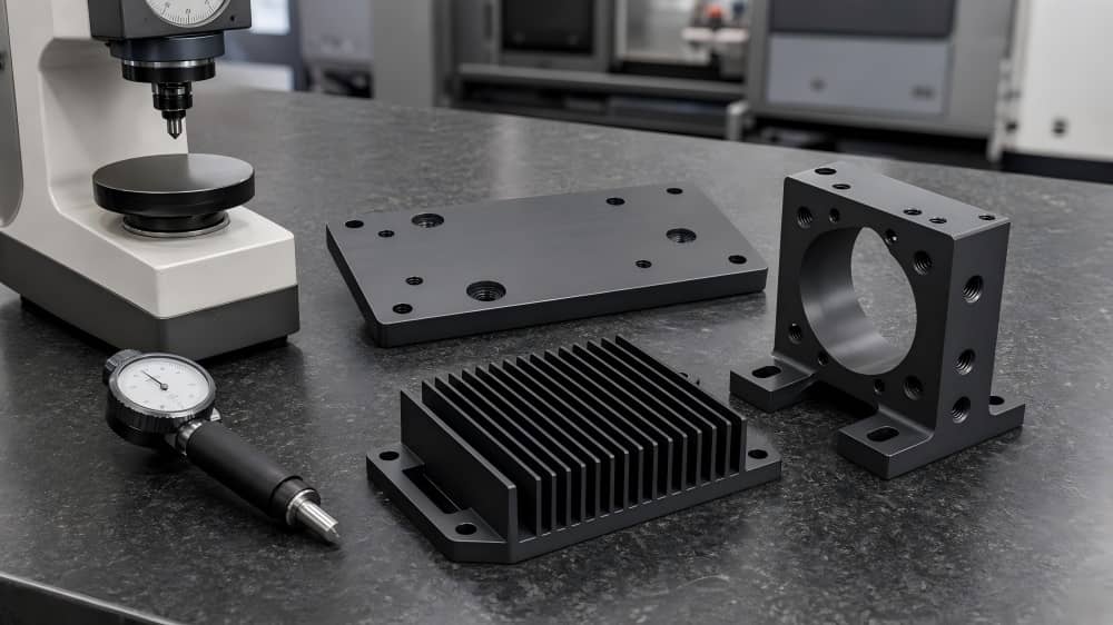
All responsible stages of the inspection of the CNC machining process, and not only the final visual inspection stage, should be undertaken. All parts with a tolerance of ± 0.05 mm must be inspected dimensionally and for functional features according to the engineering drawing.
| Inspection Stage | Key Inspection Focus |
| Before machining | Material identification, raw stock condition, drawing review |
| After first-side machining | Datum features, mounting surface, external profile |
| After second-side machining | Cooling fin geometry, locating steps, hole positions |
| Before anodizing | Critical dimensions, surface condition, burr removal |
| After anodizing | Final dimensions, coating appearance, hole condition |
| After secondary hole cleaning | Final hole dimensions and surface integrity |
The detection method should be matched with the features and tolerance requirements. According to the drawing requirements, the detection methods can include calibrated dimension-measuring tools, height measurement, coordinate measuring equipment, or special measuring tools. For precision parts, the final acceptance determination should be based on the finished parts and their corresponding drawing requirements, rather than merely relying on the measurement results before anodizing treatment.
What Should Be Considered When Machining Thin-Wall Aluminum Components?
The lessons from this Al 5083 project apply to other aluminum components with thin walls, cooling fins, narrow channels, and precision mounting features.
Before production, manufacturers should evaluate:
- Material condition: Consider the raw material’s condition and potential residual stress.
- Part geometry: Identify thin sections, deep pockets, narrow gaps, and unsupported features.
- Machining sequence: Plan roughing, repositioning, and finishing operations to minimize distortion risks.
- Fixture design: Support the component securely while avoiding excessive clamping pressure.
- Surface treatment: Include anodizing or other finishing operations in the dimensional-control plan.
- Inspection requirements: Define how all specified tolerances will be verified after the complete manufacturing process.
For related manufacturing capabilities, see JTR Machine’s CNC Milling Service, CNC Precision Machining, and Material Options.
Frequently Asked Questions
Q1: Why do thin aluminium parts become deformed after CNC machining?
The deformation of thin aluminium parts can be caused by the reshaping of residual stress, the action of cutting forces, and the development of heat during the machining process. Removing material can also reduce structural stiffness, making remaining sections more susceptible to clamping and tool pressure.
Q2: How to reduce deformation during CNC machining of aluminium cooling fins?
Use appropriate cutting tools, limit the cutting engagement, take multiple shallow cuts, use stable workholding, and ensure good chip evacuation. Incorporate fin thickness, spacing, and geometry into your machining strategy.
Q3: Will the size of aluminium parts change due to anodising?
Yes. Anodising creates an oxide layer on the aluminium surface that can alter external dimensions and decrease hole sizes. The degree of this depends on the alloy and anodising process, so dimensional allowances should be agreed on before production.
Q4: Why is secondary hole cleaning sometimes required after anodizing?
Anodizing can affect the final opening size of precision holes. Where the drawing and process plan require it, controlled secondary hole cleaning can restore the specified final hole condition. The operation must protect the surrounding coating and maintain dimensional accuracy.
Conclusion: Deformation Control Starts With Process Planning
Aluminum deformation during CNC machining is not caused by one factor alone. It is influenced by material stress, part geometry, cutting forces, chip removal, fixture design, machining sequence, and surface treatment. The Al 5083 cooling component project demonstrates how these factors can be addressed through five connected controls: thin-wall fin machining, effective chip evacuation, repeatable two-sided positioning, mounting surface flatness control, and anodizing dimensional compensation.
At JTR Machine, precision CNC machining is considered a complete manufacturing process – covering every step from material and drawing review to machining, surface treatment, and final inspection.
If your project involves thin-walled aluminum components, heat dissipation fins, precision installation structures, or anodized parts, please feel free to contact JTR Machine to discuss your drawings, material requirements, tolerance standards, and manufacturing processes.