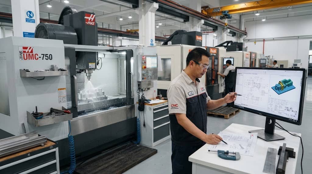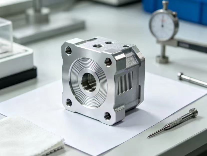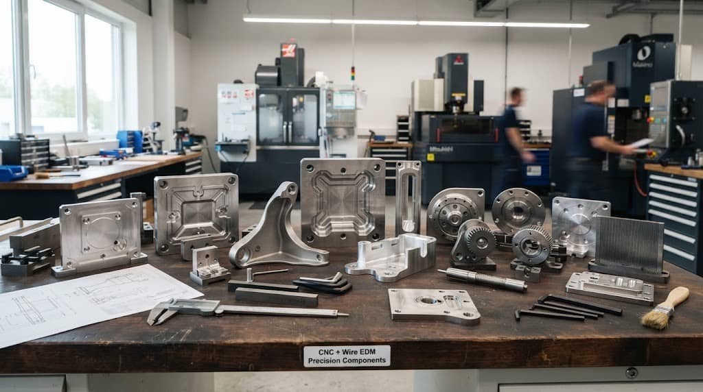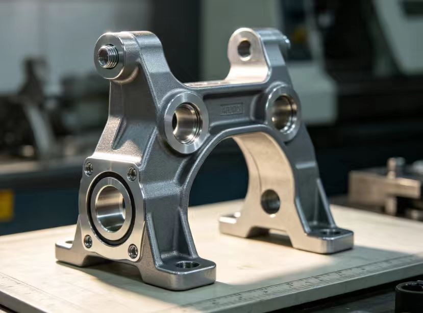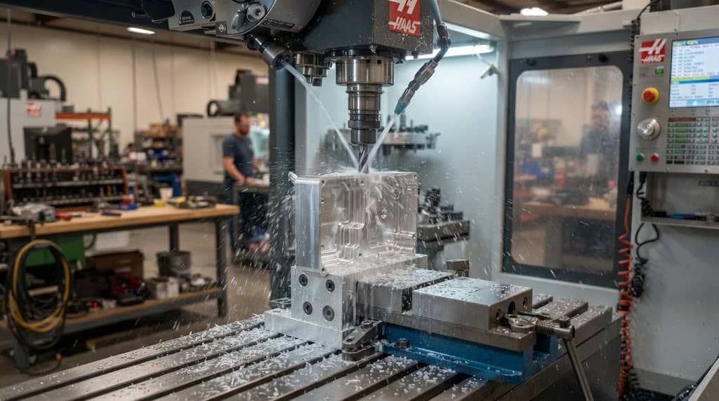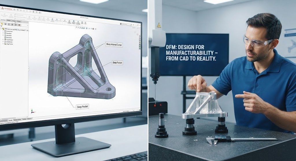


The creation of a CAD model serves as the initial stage for CNC machining, yet the production-ready file must contain information that goes beyond the basic shape of the part. The manufacturer must obtain a complete understanding of the essential materials, all critical measurements, surface processing needs, inspection protocols, production numbers, and current revision status.
A complete and clean CAD submission allows for faster quotation and DFM review processes, which results in fewer engineering questions and manufacturing errors and shorter revision times. The checklist helps engineers who need to prepare parts for CNC milling and turning and multi-axis machining by showing them how to get their files ready for manufacturing.
Choose the Right CAD File Format
The first step is to provide a file format that preserves the part geometry accurately and can be reliably imported into the manufacturer’s CAD/CAM system.
Common formats include:
- STEP (.step/.stp): A widely used neutral format for transferring solid models between different CAD systems.
- IGES (.igs/.iges): Useful for transferring surfaces and geometry, although STEP is often preferred for modern solid-part workflows.
- Parasolid (.x_t/.x_b): Useful when the manufacturer’s software supports Parasolid-based modeling.
- Native CAD files: SolidWorks, NX, CATIA, Creo and other native formats can be useful when specifically requested.
For most custom CNC projects, a neutral 3D format such as STEP is a practical choice. However, the best format ultimately depends on the manufacturer’s CAM software and the complexity of the model. The file should also use the correct units. A model created in millimeters but interpreted as inches can create a major manufacturing problem before machining even begins.
Practical check: Confirm the file format, units, scale, and model orientation before submission.
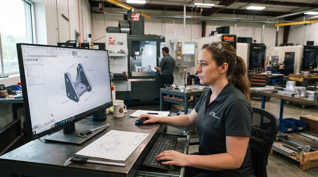
Make Sure the CAD Model Is the Final Revision
One of the simplest but most costly mistakes is sending the wrong revision. Before uploading a CAD file, confirm that the model represents the design that should actually be quoted or manufactured. This is particularly important when several engineers or suppliers are working on the same project.
Check the following:
- Part number and revision
- Design release status
- Overall dimensions
- Hole and feature locations
- Number of bodies
- Latest design changes
- Corresponding 2D drawing revision
Avoid sending obsolete versions together with the current model unless the relationship between them is clearly explained.
A useful practice is to use consistent file names, such as: Part_Number_Revision_Material
For example: JTR-1025_REV-B_6061-T6.step
This gives the manufacturing team an immediate reference when several parts are being quoted simultaneously. Before production, the final model should also be checked against the manufacturer’s CNC machining design guidelines.
Include a 2D Drawing When Manufacturing Requirements Are Not Fully Defined in the Model
A 3D model defines the physical geometry, but it may not communicate every manufacturing requirement. A 2D engineering drawing should be included when the part requires information such as:
- Critical dimensions
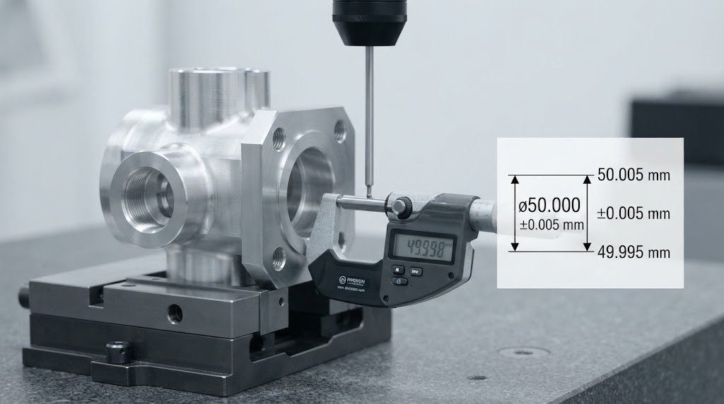
- Dimensional tolerances
- GD&T
- Dimensional tolerances
- Surface roughness
- Thread specifications
- Material grade
- Heat treatment
- Surface treatment
- Special inspection requirements
For example, a CAD model may clearly show a 20 mm hole, but the manufacturer may still need to know whether the hole requires a general tolerance, a specific positional tolerance, a reamed finish, or a particular fit.
This leads to an important distinction: The 3D model defines the geometry; the engineering drawing defines the manufacturing requirements that cannot be understood from geometry alone.
For simple parts with fully defined digital manufacturing data, a 2D drawing may not always be necessary. For precision or functional components, however, it can significantly reduce ambiguity.
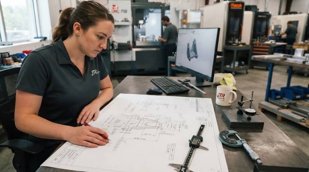
Define Material and Post-Processing Requirements
Material should never be left to interpretation. Instead of specifying only “aluminum,” identify the required grade and condition where relevant, such as:
- 6061-T6 aluminum
- 7075-T6 aluminum
- 304 stainless steel
- 316 stainless steel
- POM
- PEEK
- Brass
- Titanium
Material selection affects machining behavior, dimensional stability, surface finish, cost, and the appropriate production process.
The same principle applies to post-processing. Clearly identify any required:
- Anodizing
- Powder coating
- Plating
- Passivation
- Sandblasting
- Brushing
- Heat treatment
- Stress relieving
- Deburring
- Special cleaning
If a cosmetic surface is important, identify the surfaces and the required finish rather than assuming that the manufacturer will know which areas are critical. For parts requiring anodizing, plating, passivation or other treatments, review the available CNC surface finishing options before finalizing the drawing. These requirements can also affect the quotation, so they should be defined before manufacturing begins.
Check the CAD Model for Manufacturing Information and File Quality
Before submitting the model, perform a final digital inspection. The model should contain only the information needed to manufacture the intended part. Remove or clearly identify unnecessary construction elements, reference geometry, hidden bodies, obsolete configurations, and unrelated components.
Also check for:
- Open or broken surfaces
- Duplicate bodies
- Missing features
- Incorrect holes
- Incorrect fillets or chamfers
- Unintended gaps
- Suppressed features
- Incorrect assembly references
For a multi-body assembly, make sure the manufacturer can distinguish individual production parts from reference components. A clean CAD file is particularly important when the model will be converted into CAM data. Ambiguous or incomplete geometry can trigger additional engineering clarification and delay the quotation process.
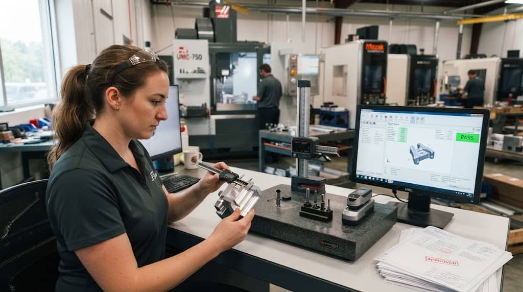
Identify Critical Features and Manufacturing Priorities
Not every feature on a CNC part has the same functional importance. If a hole controls the position of an assembly, a mounting surface determines alignment, or a bore must mate with another component, identify that requirement clearly in the drawing or manufacturing documentation. This helps the manufacturer understand where process control and inspection should receive the greatest attention.
It is also important not to apply extremely tight requirements to every dimension simply because the CNC machine is capable of high precision. Tight requirements should be reserved for features where they provide a functional benefit. JTR’s published CNC guidance likewise distinguishes between general machining requirements and tighter tolerances for critical features.
A good drawing therefore answers two questions:
- What must be controlled tightly?
- Which dimensions can use normal manufacturing tolerances?
This distinction can improve both manufacturability and cost.
Provide the Information Needed for an Accurate CNC Quote
A CAD file alone may not be enough to prepare a meaningful production quotation. At minimum, provide:
| Information | Why It Matters |
| 3D CAD model | Defines part geometry |
| 2D drawing | Defines manufacturing requirements |
| Material and grade | Determines machining and material cost |
| Quantity | Affects setup and production economics |
| Surface finish | Determines secondary processing |
| Critical tolerances | Affects process and inspection |
| Inspection requirements | Defines quality-control scope |
| Target delivery date | Helps evaluate production scheduling |
Quantity is particularly important. The manufacturing approach for one prototype can be different from that for hundreds or thousands of parts. For example, a prototype may prioritize flexibility and rapid turnaround, while larger production quantities may justify process optimization, dedicated workholding, or more efficient machining strategies.
JTR Machine’s CNC machining service covers rapid prototyping and end-use production across 3-axis, 4-axis and 5-axis CNC equipment, as well as milling, turning and Wire EDM processes. Providing complete project information allows the manufacturer to evaluate the most appropriate production route rather than quoting the CAD geometry in isolation.
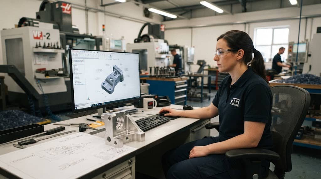
Use a Final CNC CAD Submission Checklist
Before sending a CAD package, run through this final checklist.
CAD Model
- Final design revision confirmed
- Correct units and scale
- Correct part orientation
- Complete solid geometry
- No obsolete or unnecessary bodies
- No obvious geometry errors
Engineering Drawing
- Critical dimensions identified
- Applicable tolerances specified
- GD&T included where necessary
- Thread specifications defined
- Surface requirements identified
- Inspection requirements stated
- Material and Finishing
Material grade specified
- Heat treatment defined if required
- Surface treatment specified
- Deburring or cleaning requirements stated
Production Information
- Quantity provided
- Target delivery date provided
- Packaging requirements identified if applicable
- Special quality documentation requested if required
The final objective requires more than sending a CAD file that CNC manufacturers should access. The process requires a ready-to-manufacture data package that minimizes the need for any additional explanations. The manufacturer achieves better efficiency when they have all the necessary information about CAD models and drawings, material specifications, finishing requirements, quantity, and inspection expectations to start their work, from design review through DFM analysis, quotation, and production.
For custom CNC projects, JTR Machine allows customers to submit 2D/3D files for manufacturing review and provides DFM analysis and quotation before production.
FAQ
Q1: What CAD file format is best for CNC machining?
STEP is a widely used choice because it provides a neutral format for transferring 3D solid geometry between different CAD systems. The preferred format can vary depending on the manufacturer’s software and production workflow.
Q2: Do I need a 2D drawing if I already have a 3D CAD model?
Not always. However, a 2D drawing is highly useful when the part has critical tolerances, GD&T, surface-finish requirements, special threads, inspection requirements, or other specifications that are not fully defined by the 3D model.
Q3: What information should I include when requesting a CNC quote?
Provide the 3D CAD model, 2D drawing when applicable, material and grade, quantity, critical tolerances, surface treatment, inspection requirements, and desired delivery schedule.
Q4: Can a CNC manufacturer work directly from a CAD file?
Yes, when the model contains sufficient manufacturing information. However, complex or precision parts often require additional drawings and specifications so the manufacturer can correctly interpret functional requirements.
Q5: How can I reduce delays when submitting a CNC CAD file?
Use the final design revision, confirm units and geometry, clearly identify material and finishing requirements, specify critical dimensions, and provide quantity and inspection requirements with the CAD package.
Q6: Does CAD file preparation affect CNC machining cost?
Yes. Clear manufacturing requirements can reduce clarification and rework. The geometry itself also influences machining strategy, setup requirements, tooling, processing time, finishing, and inspection. A well-prepared CAD package helps the manufacturer evaluate these factors before production.