In aerospace manufacturing, minimizing component weight while maintaining structural integrity is a primary design objective. To achieve this, modern aircraft components feature integrated, lightweight topologies with complex geometries. As an experienced CNC machining engineer specializing in this sector, I am frequently asked by procurement teams and field engineers whether a specific structural component, such as an aircraft bracket, strictly requires multi-axis processing. The technical reality of the shop floor dictates that 5-axis aerospace machining is no longer an optional luxury; it is a manufacturing necessity.
When global tier-1 suppliers seek a 5-axis CNC machining service, they require verified technical capabilities, strict tolerance control, and comprehensive risk mitigation strategies for high-value materials. This article provides a direct engineering analysis of why complex aircraft components demand advanced multi-axis production and how these systems overcome the physical limitations of traditional milling.
What is 5-Axis CNC Machining, and Why Does Aerospace Need It?
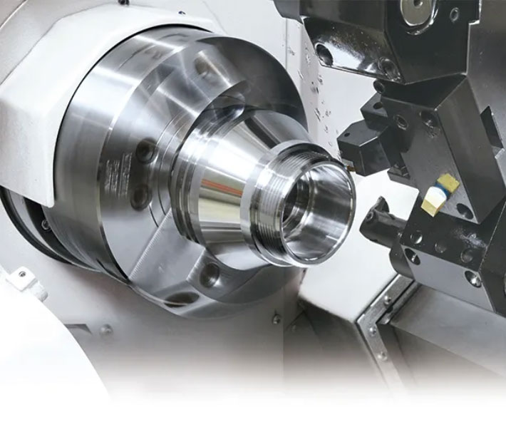
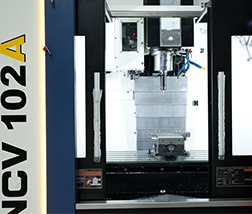
Conventional CNC milling machines work on three linear axes, X, Y, and Z. Vertical or horizontal machining centers are very efficient in the machining of prismatic components, but they are kinematically limited in the machining of complex geometry. A 5-axis mill has two additional rotational axes. These are usually referred to as the A-axis, which tilts about the X-axis, and the B-axis or C-axis, which rotates about the Y or Z-axis. In this cinematic setup, the cutting tool can approach the workpiece from any direction within a hemispherical working area.
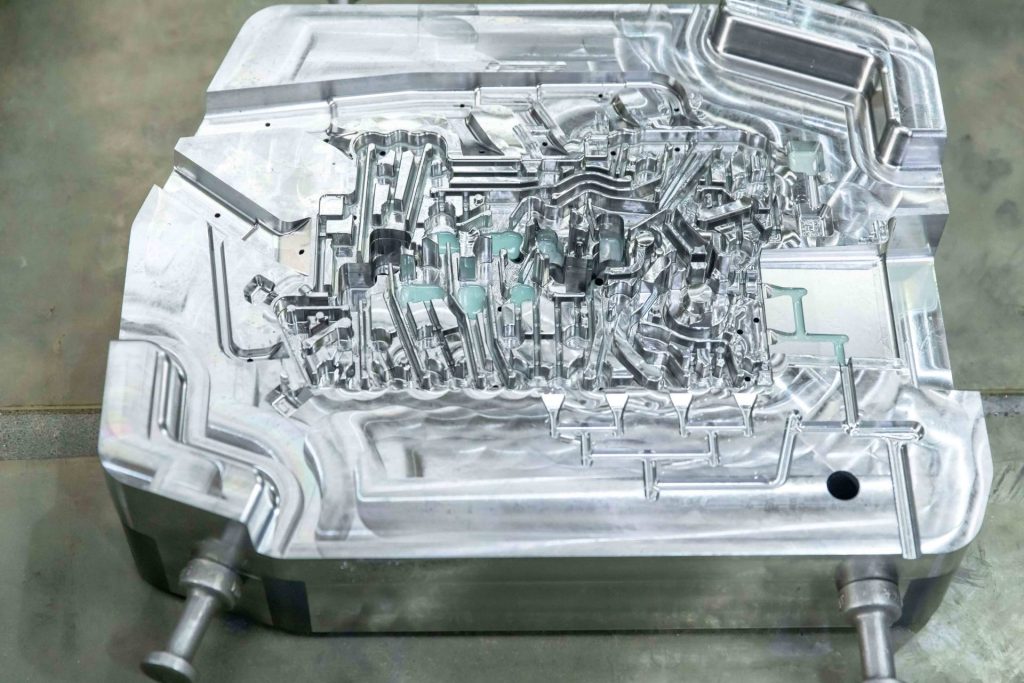
Aerospace components such as structural brackets, impellers, and bulkhead frames are characterized by organic contours, free-form surfaces, variable-angle draft webs, and deep internal cavities. The processing of these features on a 3-axis or 4-axis machine presents serious risks to production:
- Accumulated Setup Errors: Machining a multi-sided aircraft bracket on a 3-axis machine involves multiple setups and dedicated fixturing to move the part to machine each side. You are accumulating alignment variances every time you manually reposition it. It is compounded geometric dimensioning and tolerancing ( GD&T ) errors.
- Tool Reach is not Sufficient: On a 3- axis machine, the tool axis cannot be changed. If you have angled features or deep pockets, the machine spindle can’t go around anything in the way, and you get tool collisions or unmachined stock.
These limitations can be removed with a dedicated 5-axis CNC machining service by combining operations in one setup, retaining the exact spatial relationship between different geometric features.
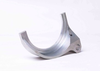
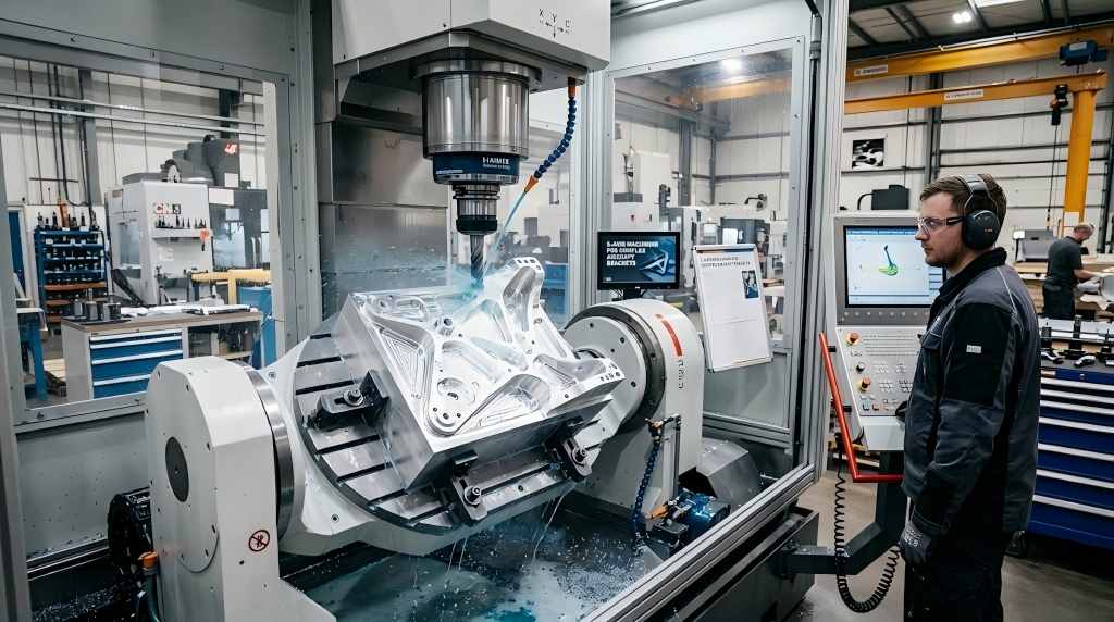
Why an Aircraft Bracket Absolutely Requires 5-Axis Milling
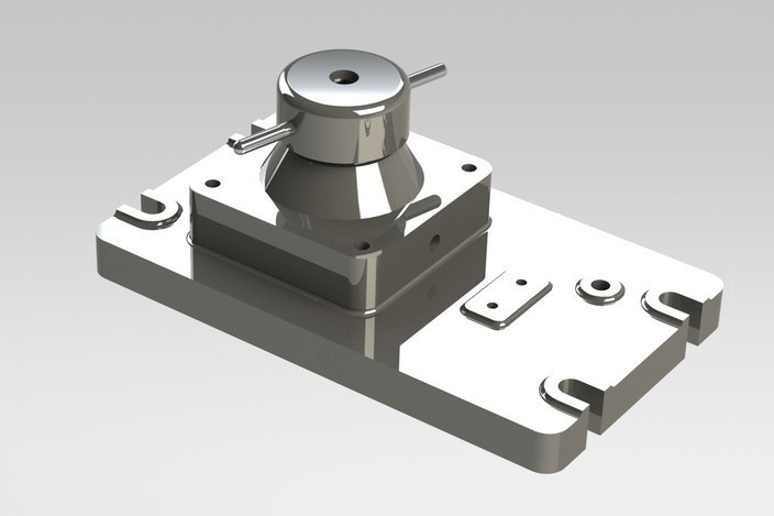
5-axis machining is not only desirable, but technically necessary. We will demonstrate this by examining the production sequence of a typical structural aircraft load-bearing bracket. These components transfer the critical aerodynamic forces from the fuselage to the control surfaces and require high strength-to-weight ratios.
Challenge 1: Deep Cavities & Thin Walls
To meet strict weight limits, aerospace engineers design brackets with deep pocket configurations bounded by thin pocket walls, often under 2.0 mm in thickness.
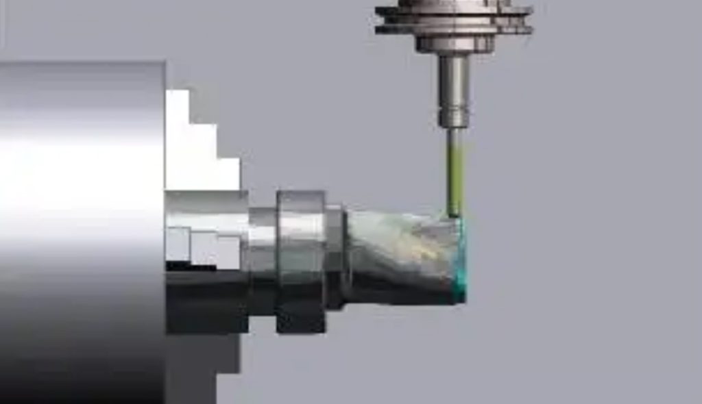
- The 3-Axis Failure Mode: In a standard 3-axis configuration, milling a deep cavity requires a long, extended-reach cutting tool to clear the upper flanges. Long tools have reduced static and dynamic rigidity. According to mechanical engineering principles, tool deflection increases cubically with its unsupported length. This lack of rigidity causes severe tool chatter, poor surface finish, accelerated tool wear, and thin-wall structural distortion.
- The 5-Axis Solution: A 5-axis mill either tilts the spindle head or the trunnion table. The adjustment in the positioning enables a much shorter and higher-rigidity cutting tool to enter the deep cavity with an optimal angle. The process is free from chatter due to the high rigidity of the tool; wall thickness tolerances of ±0.02 mm are maintained, and mechanical deformation of the thin-walled structure is avoided.
Challenge 2: Eliminating Setup Errors for Strict Geometrical Tolerances
Aircraft brackets contain multiple critical bore holes, mating faces, and alignment slots that must conform to strict true-position tolerances (frequently within 0.03 mm relative to primary datums). When utilizing separate fixtures across multiple machine setups, the tolerance stack-up from fixture positioning, part clamping variations, and machine origin shifts makes compliance nearly impossible.
5-axis processing utilizes the single-setup principle. By clamping the raw stock or forging once, the machine accesses five sides of the part sequentially. The relative positioning of every hole, slot, and face is controlled strictly by the linear and rotational positioning accuracy of the machine encoders, eliminating human indexing errors completely.
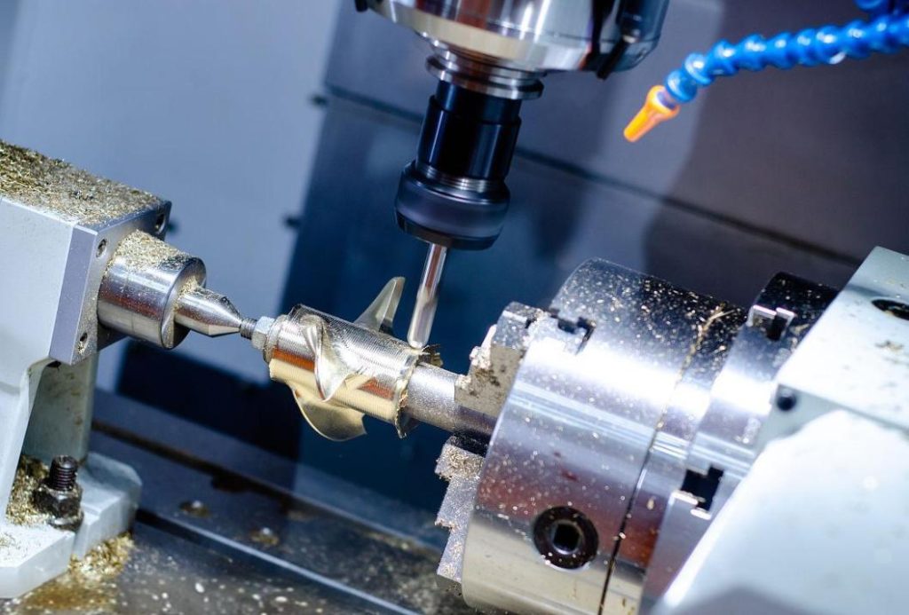
Challenge 3: Maintaining Constant Surface Speed on Organic Shapes
When milling the complex, organic external contours of an aircraft bracket, the cutting tool must maintain a constant surface speed (Vc) to ensure uniform material removal rates and surface finishes on a 3-axis machine, as the ball-nose end mill moves over a curved surface, the effective cutting point shifts toward the center tip of the tool, where the rotational velocity drops to zero, causing rubbing rather than efficient shearing.
5-axis continuous machining solves this by dynamically tilting the tool axis relative to the surface normal vector. This system keeps the contact point at the optimal diameter of the ball-nose cutter to maintain a stable Vc to avoid surface burnishing and ensure the surface finish meets the stringent Ra 1.6 μm aerospace standard without manual polishing.
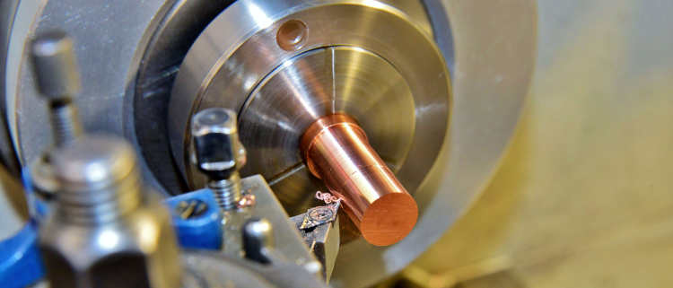
Overcoming Titanium and Inconel with 5-Axis Technology
Aerospace brackets and structural components demanding advanced engineering alloys are subjected to severe cyclic loading and thermal environments. These materials represent extreme mechanical machinability challenges that require multi-axis tool path strategies to manage tool stress and heat generation.
| Material Group | Typical Alloy | Mechanical Characteristics | 5-Axis Machining Mitigation Strategy |
| Titanium Alloys | Ti-6Al-4V (Grade 5) | Low thermal conductivity, high chemical reactivity at elevated temperatures, high cutting forces. | Continuous 5-axis tool orientation optimization prevents localized heat buildup. Maintains exact engagement angles to maximize tool flank wear predictability and extend tool life. |
| Nickel-Based Superalloys | Inconel 718 | Rapid work-hardening behavior, high shear strength at temperature, abrasive microstructures. | Utilizes high-rigidity 5-axis tool paths combined with trochoidal milling strategies to distribute tool load evenly, mitigating notch wear and avoiding tool breakage. |
| Aerospace Aluminum | 7075-T651 | High residual stress from rolling/forging, prone to structural warping during heavy material removal. | Employs high-speed 5-axis adaptive milling paths to remove material rapidly and symmetrically, balancing internal residual stresses to prevent part distortion. |
What to Look for in a 5-Axis CNC Machining Service for Aerospace Projects
While auditing an appropriate manufacturer for sensitive aircraft programs, purchasing professionals will have to look for additional requirements apart from the number of machines:
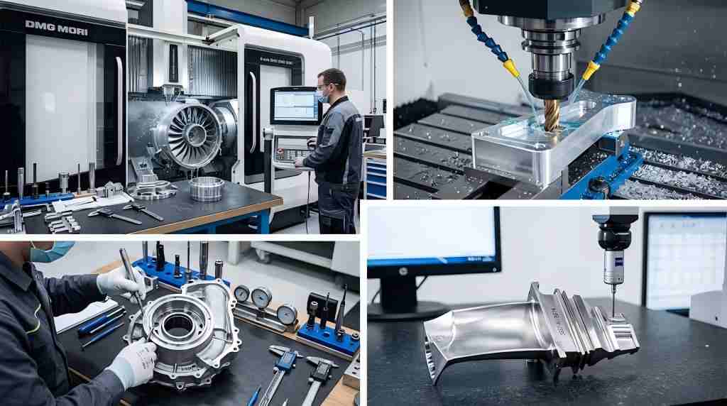
- Equipment Classification and Kinematics Rigidity: Make sure that the service provider runs high-class 5-axis milling equipment, such as those made by DMG MORI, Makino, Hermle, and Matsuura. The machines should come with thermal stabilization equipment, high torque and power direct-drive spindles, and high-resolution linear scales for volumetric stability during full load operation.
- Certification and Quality System: It is mandatory for the company to have an AS9100D quality management system certification. This standard ensures that there is full traceability of batches, NDT procedures are followed, and FAI is done according to AS9102 standards.
- Advanced CAM Programming and Simulation Integration: Programming complex multi-axis paths requires specialized software suites like Hypermill or Mastercam. Moreover, the manufacturer must perform full simulation using such programs as VERICUT, where the exact kinematic simulation allows verifying the clearance and avoiding possible machine crashes.
- Metrological Precision and Volumetric Verification: The provider must have local coordinate measuring machines (CMM) with continuous scanning or 5-axis probing head capability to measure geometrical features relative to a native 3D CAD model.
Multi-axis milling is the fundamental manufacturing process that fulfills the modern aviation requirements for lower component weight, higher structural stiffness, and longer service life – from structural brackets in aircraft to sophisticated parts for turbines. Accurate five-axis processes ensure structural parts are precisely formed to engineering specifications, while maximizing production throughput.
Frequently Asked Questions (FAQ)
Q1: What specific geometric tolerances can be achieved with a 5-axis aerospace machining service?
A1: A high-tier 5-axis CNC machining center operating in a climate-controlled facility can consistently maintain linear positioning tolerances within ±0.005 mm (0.0002 inches) and rotational indexing tolerances within ±2 arc-seconds. Real-world true-position tolerances for critical bore holes are typically held within 0.02 mm relative to primary datums.
Q2: How does 5-axis machining reduce overall production lead times for complex aerospace brackets?
A2: Although it takes more time to program and simulate the first phase of CAM programming and simulation compared to 3-axis programming, the use of 5-axis machining avoids the necessity for designing and making several modular setups and fixtures. By reducing the whole process of manufacturing to one setup, an overall time saving of up to 40%-60% is achieved.
Q3: Why is AS9100D certification mandatory for shops providing 5-axis aerospace machining?
A3: The AS9100D standard incorporates the ISO 9001 standard while implementing strict risk management, critical items control, and configuration management specific to the aerospace, defense, and space industry sector. The AS9100D makes sure that each stage of the 5-axis machining process is documented from forging through to the ultrasonic testing stage to avoid any product defects.