

As a CNC machine operator working on the shop floor daily, I frequently see engineering drawings that look perfect on a computer screen but present severe manufacturing challenges when loaded into our CAD/CAM software. When procurement departments receive quotes for aerospace precision machining, the immediate reaction is often sticker shock.
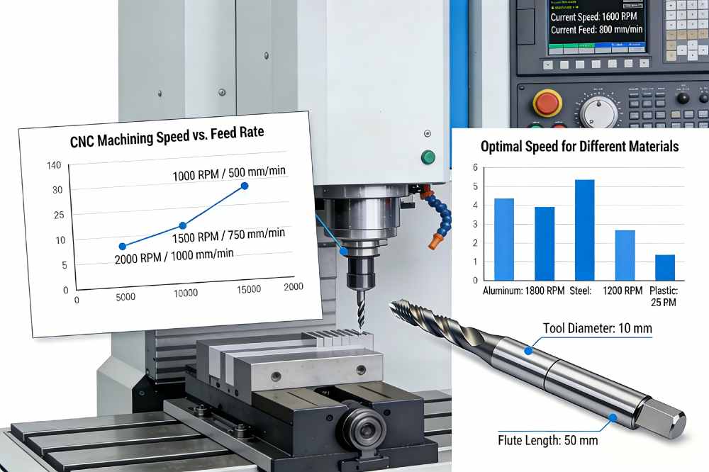
The control panel of a 5-axis CNC machine clarifies and quantifies the reasons for these high costs. Aerospace CNC machining costs are influenced by the physical realities of cutting high-strength materials and managing structural deflection, as well as mitigating extreme tool wear and executing rigid quality control protocols required under AS9100. Here is a technical review of why these parts are more expensive to manufacture, and some specific machining data and operational insight.
Heavy Metal & Tough Exotics: Why Aerospace Materials Eat Our Tools
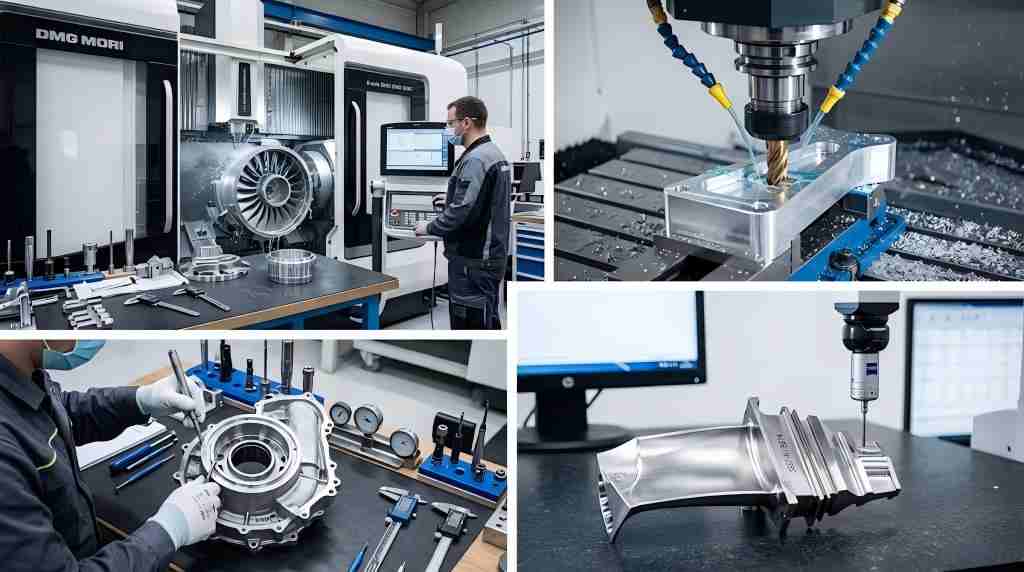
In standard commercial CNC machining services, working with Aluminum 6061 or mild steel allows for high spindle speeds, aggressive feed rates, and long tool life. In aerospace precision machining, we primarily process exotic alloys designed to withstand extreme thermal and mechanical loads. These material properties directly degrade cutting tool efficiency.
1. Titanium (Ti-6Al-4V) vs. Standard Aluminum
Titanium Ti-6Al-4V is specified for its strength-to-weight ratio and corrosion resistance, but its thermal conductivity is extremely low (≈6.7 W/m⋅K). When a solid carbide end mill engages a titanium workpiece, the friction-generated heat cannot dissipate through the material or the chip. Instead, the heat concentrates directly on the tool’s cutting edge, often reaching temperatures above 800℃. This induces rapid thermal cracking and adhesive tool wear. To avoid such an extreme measure, tool breakdowns will likely occur; it would be best to cut our cutting speed to a small measurable value, but high cutting rates increase cycle times exponentially.
2. The Challenge of Machining Superalloys (Inconel 718)
Superalloys such as nickel alloy 718 have the advantage of being able to withstand high temperatures due to the yield strength that is preserved even when working at high temperatures. Work hardening is a significant disadvantage of Inconel since Inconel shows extensive work hardening during the shearing operation. The operator may experience chipping if the feed speed is set too slow.
| Material Designation | Cutting Speed (Vc in m/min) | Typical Tool Life (Minutes per Edge) | Primary Wear Mechanism |
| Aluminum 6061-T6 | 300−800 | 120−240 | Built-up edge (BUE), minor abrasive wear |
| Titanium Ti-6Al-4V | 40−80 | 30−45 | Thermal degradation, chipping, notch wear |
| Inconel 718 | 20−40 | 15−30 | Rapid work hardening, depth-of-cut notch wear |
The “Buy-to-Fly” Ratio: Turning 90% of Premium Material into Chips
A major cost driver in aerospace structural components is the design shift toward monolithic components. To eliminate fasteners, rivets, and welded joints—which represent potential fatigue failure points—engineers design complex components to be machined out of a single, solid forged block of raw material.
This practice results in a high buy-to-fly ratio. The buy-to-fly ratio, also known as ‘the weight ratio, is the ratio of the raw stock that is purchased over the finished part that can be used in the aircraft. Presently, in aerospace engineering, this figure forces itself between 10:1 and 20:1.
For example, when machining an aircraft bulkhead or wing spar from an aerospace-grade Aluminum 7075-T6 forging weighing 200 kg, the final part weight after machining may only be 15 kg. The remaining 185 kg of high-value, certified material is reduced entirely to chips. The cost of purchasing the premium raw block, combined with the machine hours required to remove 90% or more of the material volume, represents a large percentage of the final per-part cost.
Battling Thin-Wall Deformation and Internal Stress
Aerospace structural parts frequently feature deep cavities separated by thin-wall ribs or pockets with a wall thickness of 1.5 mm or less. Machining these thin features introduces structural instability and part deflection.
When we remove the exterior skin of a forged or rolled plate, the balanced internal residual stresses within the raw material are disrupted. This causes the component to warp, bow, or twist during or after the machining cycle. Additionally, the thin walls lack structural rigidity and are prone to chatter (high-frequency vibration) when subjected to the radial cutting forces of the end mill. Chatter destroys the required surface finish (Ra values typically specified at 0.8−1.6 μm) and can cause the thin walls to fracture.
To control thin-wall deformation, we cannot use a linear, single-pass machining strategy. Operators must implement a highly sequenced multi-stage process:
- Rough Machining: Remove the bulk of the material uniformly from both sides to distribute residual stress release evenly.
- Stress Relieving / Age Hardening: Remove the part from the machine fixture and subject it to a thermal stress-relief cycle in a furnace.
- Semi-Finishing passes: Re-clamp the part using specialized workholding and machine to within 0.25 mm of final dimensions.
- Final Precision Pass: Use high-speed, low-depth-of-cut finishing passes to achieve the final geometric tolerances without generating excessive cutting forces.
This multi-step sequence multiplies setup times, handling costs, and overall machine utilization hours.
The Hidden Costs: 5-Axis Machines, Specialized Fixtures, and Strict AS9100 QC
The machine shop infrastructure required to support aerospace contracts involves capital investments that must be factored into the hourly shop rate.
1. Rigid 5-Axis Kinematics
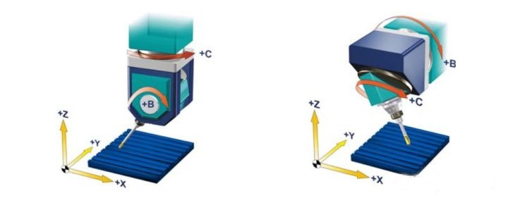
Aerospace components have complex, continuous curved geometries that follow aerodynamic profiles. These cannot be produced on standard 3-axis CNC mills. They need high-end 5-axis simultaneous machining centers. These machines need to have rigid spindles to address titanium machining challenges while achieving linear positioning accuracies of ±0.002 mm or better. The acquisition, maintenance, and thermal compensation software calibration costs for these machine tools are high.
2. Custom Fixturing & Workholding
Standard vices and clamps are inadequate for holding non-rigid, thin-walled aerospace parts. When a machine operator uses the normal hydraulic pressure on a thin-wall structure, the component distorts in the fixture, gets machined in the distorted form, and is rejected immediately as defective upon releasing the clamping pressure. We must design and CNC machine dedicated modular vacuum fixtures or matching profile jaws to support the part uniformly across its entire geometry.
3. 100% Traceability and NDT
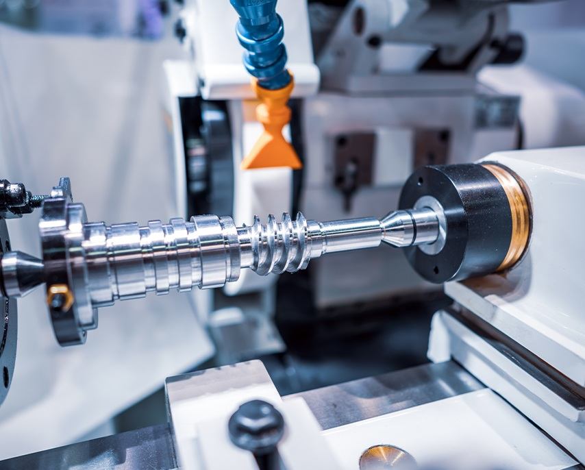
Every aerospace part requires a complete manufacturing documentation trail. A CNC machining service provider operating under AS9100 must maintain full material traceability. This includes Mill Test Reports (MTR) verifying the chemical composition of the raw material heat lot. After machining, parts undergo coordinate measuring machine (CMM) dimensional validation. You can then send them for Non-Destructive Testing (NDT), for example, Liquid Penetrant Inspection (LPI), or ultrasonic testing to check for subsurface micro-cracks before the final process of anodizing, or any other chemical bath.
How Designers Can Reduce Aerospace CNC Machining Costs
Components used in aerospace must meet high levels of performance criteria, but it is possible for design engineers to change some of the geometry to ensure efficiency and minimal tool wear in the machining process.
1. Avoid Sharp Internal Corners
When a pocket contains a sharp 90° internal vertical corner with a small radius (e.g., R1 mm or less), the CNC operator is forced to use a very small diameter end mill. Small tools possess poor rigidity and thus have to be fed slowly to avoid breakage. Moreover, with the increase in the radius of curvature, the cutting angle becomes extremely high, causing tool vibration and resulting in tool failure. Designing corners with a larger radius allows shops to use larger, rigid indexable end mills, maximizing the material removal rate (MRR).
2. Relax Tolerances Where Permitted
Specifying a tight tolerance, for example, ±0.005mm across non-critical clearance faces, will increase cost exponentially. The machinist has to make many passes with the spring, stopping the machine frequently to measure the part and to adjust the wear offsets of the tool by hand. Tight tolerances should be reserved strictly for critical mating faces or bearing bores.
3. Standardize Wall Thickness
Varying wall thicknesses across a single structural pocket requires complex toolpath programming and multiple tool changes. Standardizing wall profiles enables the use of uniform roughing and finishing routines, reducing both programming overhead and physical cycle time on the shop floor.
Aerospace precision machining costs are a direct reflection of the rigorous physical and regulatory environments governing the aviation and defense industries. The combination of poor machinability ratings of materials, high waste of materials, need for controls against thin wall distortion, and complete traceability requirements leads to a very expensive manufacturing environment.
FAQ
Q1: Which aluminum alloy is best for lightweight aerospace structures?
A1: Aluminum 7075-T6 is the primary choice for structural components due to its high yield strength, which is comparable to certain steels, though it exhibits lower corrosion resistance than 6000-series alloys. For parts requiring superior weldability and marine corrosion resistance, 5-series (such as 5083) and 6-series (such as 6061) are utilized.
Q2: What effect does tool wear have on CNC machining cost?
A2: When cutting titanium or Inconel, special solid carbide end mills with advanced physical vapor deposition (PVD) coatings can go dull after 20 to 30 minutes of continuous cutting time. The cost of replacing consumables and the downtime of the machine for the operator to perform tool changes and recalibrate tool setters adds a significant amount of labor and material cost to the invoice.
Q3: How long does it take to make complex aerospace CNC parts?
A3: Usually, the lead time is 6 to 12 weeks long. This duration depends on certified material acquisition, manufacturing fixtures design, multiple cycles of stress relief, and testing as prescribed by AS9100.